EasyManua.ls Logo

Carrier SUPRA 950Mt - Refrigerant Circuit

Carrier SUPRA 950Mt
92 pages
To Next Page IconTo Next Page
To Previous Page IconTo Previous Page
Loading...
2
-
3
2
6
2
-
-
6
1
1
X
X
-
-
2
0
(
0
3
/
0
4
)
-
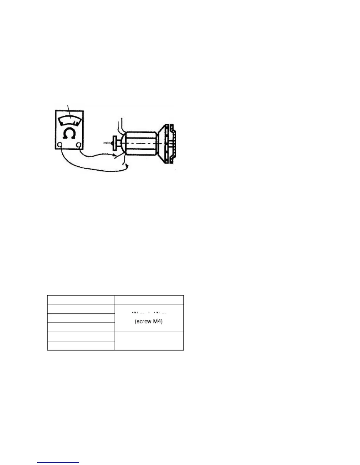
Cut out one side of the diodes.
-
Check those diodes with an ohmeter.
-
The diode is conforme if it has an infinite
resistance in one direction and a resistance of
0 in the other. If the resistance is infinite in
both directions or if it is at 0 in both directions,
the diode is broken.
e.
Che
ck
of
the winding
res
ist
or
(se
e
gene
rat
or
resistance values section 2.5)
OHMETER
ROTOR
With an ohmeter:
-
Stator: by the output wires (Check the
connection).
-
Rotor: requires to remove the rotor and to cut
out the diodes.
f.
Che
cki
ng of the c
onnec
tor
s
If the generator would not provide electricity, check
that the connectors are well crimped
g.
Asse
mbly phas
e
-
Mount the stator/rotor to the flange fasten the
4 bolts.
-
For the reassembly of the tested generator,
the tightening torques (N.m) for the fixation of
the front cover, stator and rear cover onto the
casing are:
Vers
ions
Torque values
54--60029--00
54--60029--01
4N.m
¦
1N.m
54--60032--00
54--00603--00
5N.m
¦
1N.m
54--00603--01
(screw
M6)
2.1
1
REFRI
GERA
NT
CIRC
UIT
2.
1
1.
1
Co
oli
ng
mod
e
when cooling, the unit operates as a vapor compres-
sion refrigeration system. The main components of the
syst
em
are
the
reci
pro
cati
ng
com
pres
sor
,
air-
coo
led
conden
ser, thermostatic
expansi
on valve,
direct expan-
sion evaporator, and liquid line solenoid valve.
The
co
mp
re
sso
r
rai
se
s
the
tem
pe
rat
ur
e
an
d
pre
ssu
re
of
the refrige
ran
t
and it
pas
ses
thro
ugh a
no
rma
ll
y
op
en
Ma
in
He
at
V
al
ve
(M
HV)
,
thr
ou
gh
a
ch
ec
k
valve into the condenser. The condenser fan circulates
sur
rou
ndi
ng
air
ove
r
the
out
sid
e
of
the
con
den
ser
tube
s.
Heat transfer is then established from the refrigerant
ga
s
(in
si
de
the
tub
es
)
to
the
co
nd
en
se
r
ai
r
(fl
ow
in
g
ov
er
the tubes). The
conde
nser tubes have fins
desig
ned to
im
pro
ve
the
tra
ns
fer
of
he
at.
Thi
s
re
mo
va
l
of
he
at
cau
ses
the
refri
ger
ant
to
liq
uef
y
.
Liq
uid
refr
ige
rant
flow
s
from the condenser and through a check valve to the
receiver.
The receiver stores the additional charge necessary
for low
amb
ien
t
ope
ratio
n
and for
hea
ting and
defro
st
modes. The refrigerant leaves the receiver and flows
throug
h
a
manua
l
receiv
er
shutof
f
valve (king valve).
The refrigerant then flows through the subcooler.
Th
e
su
bc
oo
l
er
o
cc
u
pi
e
s
a
p
or
ti
o
n
o
f
th
e
ma
in
co
nd
en
si
ng
co
il
su
rfa
ce
an
d
gi
ve
s
of
f
fur
the
r
he
at
to
the
passing air.
The
refr
ige
rant
then
flow
s
thro
ugh
a
filt
er-d
rie
r
whe
re
an
abs
orbe
nt
kee
ps
the
refri
ger
ant
cle
an
anddry.
The
refr
ige
ran
t
thenflows
thro
ughthe
acc
umu
lato
r
/
heat exchanger and then to the liquid solenoid valves
(LSV
).
The
se
sol
eno
ids
are
ele
ctric
all
y
ene
rgi
zed
whe
n
in cooling mode and allow the liquid refrigerant to flow
th
ro
ug
h
th
e
ex
te
rn
al
ly
eq
ua
li
ze
d
th
er
mo
st
at
ic
expansion valve (TXV), which reduces the pressure of
the liquid and meters the flow of
liqui
d refrigerant to the
evaporator to obtain maximum use of the evaporator
heat transfer surface.
The
ev
ap
or
ato
r
tu
be
s
ha
ve
al
um
in
um
fin
s
to
increase heat transfer; heat is removed from the air
ci
rc
ul
ate
d
thr
ou
gh
th
e
ev
ap
ora
tor
.
Th
is
co
ld
ai
r
is
circulated throughout the box to maintain the cargo at
the desired temperature.
Th
e
tr
an
sf
e
r
o
f
he
a
t
fr
om
th
e
ai
r
to
th
e
lo
w
tem
per
atur
e
liq
uid
refri
ger
ant
cau
ses
the
liq
uid
to
vap
ori
ze.
Thi
s
low
temp
era
ture
,
low
pre
ssu
re
vap
or
pas
ses
int
o
the
acc
umu
lat
or
tan
k.
The
com
pre
sso
r
dr
aw
s
th
e
va
po
r
ou
t
of
the
ac
cu
mu
la
tor
thr
ou
gh
a
pick-up tube which is equipped with a metering orifice.
Thi
s
ori
fice preven
ts
the accum
ula
tio
n
of
oil in
the
accumulator tank. The metering orifice is calibrated to
control the rate of oil flowing back to the compressor.
The vapor refrigerant then enters the compressor
pre
ssu
re
reg
ula
ting
val
ve
(CPR
),
whi
ch
reg
ula
tes
refr
ige
ran
t
pre
ssu
re
ente
ringthe
com
pre
sso
r,
whe
re
the
cycle starts over.

Table of Contents

Other manuals for Carrier SUPRA 950Mt

Related product manuals