Do you have a question about the CAS RW Series and is the answer not in the manual?
Lists important safety and usage precautions for operating the Road Weigher.
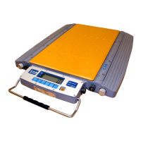
Highlights the product's small size and slim profile (60mm height).
Mentions the integration of a high-accuracy load cell for precise weight measurement.
Presents visual overviews of the RW-S and RW-L types of the Road Weigher.
Displays the detailed dimensions (L, W, H, P, P') of the Road Weigher.
Lists model, capacity, division, accuracy, size, power, running time, display, and temperature.
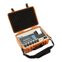
Shows illustrations of the scale, charger, battery, and connection cable.
Illustrates the wiring diagram for connecting two scales.
Illustrates the wiring diagram for connecting four scales.
Illustrates the wiring diagram for connecting six scales.
Details the steps for connecting the battery to charge.
Shows how to connect the charger to the main unit.
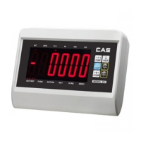
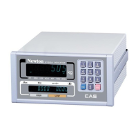
Explains the meaning of STABLE, ZERO, TOTAL indicators and weight units (kg/lb).
Describes the purpose of each key on the front panel.
Instructions on how to initiate the TEST mode.
Instructions on how to initiate the SET mode.
Step-by-step guide to access the TEST mode.
Details the keys used for navigation and execution within the test mode.
Lists the five diagnostic tests: Key, LCD, Load Cell, Serial, Printer.
Procedure and expected results for testing the LCD display.
How to perform and interpret the load cell and A/D conversion test.
Steps to test the serial interface for data transmission and reception.
Instructions for performing and verifying the printer test.
Shows the format of data printed by the device.
Instructions on accessing the SET mode via key combinations.
Details the keys used for parameter adjustment and navigation in SET mode.
Lists the configurable parameters from F01 to F14.
Details settings for primary unit, serial port, auto zero tracking, and digital filter.
Covers backlight mode, device ID, quantity of scales, and clock option.
Procedure for setting the current date and time.
Instructions for accessing the CAL mode via key combinations.
Defines key functions for navigation and value adjustment in calibration.
Lists the five calibration steps: Max Capacity, Min Division, Span Weight, Zero, Span.
Procedure to set the maximum weight capacity.
Procedure to set the minimum division value.
Setting the reference weight for span calibration.
Steps to perform zero calibration and confirmation.
Steps to perform span calibration with a set weight.
Provides reasons and solutions for errors 02, 06, 08, 13, and overload conditions.
| Brand | CAS |
|---|---|
| Model | RW Series |
| Category | Accessories |
| Language | English |