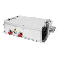
3.6.4 Main Contactor:
The main contactor is the switching element between the DC high-voltage power source
(typically a battery) and the controller. The main contactor must be sized to handle the
operating currents of the controller. In addition the main contactor must be able to open
under a fault condition. Generally only one contactor is needed, the application schematic
shows the main contactor in series with the positive path from the battery to the controller.
Cascadia Motion has successfully used the following: Gigavac GX14BA, Cascadia Motion
p/n 77-0035. The contactor must be rated to handle DC voltage, AC only rated contactors
and relays must not be used. DC rated contactors are usually polarity sensitive. That is the
normal operating current should flow in a particular direction. Refer to the contactor data
sheet for more information.
3.6.5 Main Fuse:
The DC Power input to the controller must be fused. The fuse must be
rated for the voltage of the battery as well as rated to open under the short circuit current
that the battery can produce. Generally, this fuse (or equivalent fusible link) may be a part of
the battery pack, but if the pack protection is not present or adequate, this fuse is required to
prevent a potential battery pack fire. The fuse should be rated to handle the maximum DC
input current of the controller. A semiconductor type fuse is recommended.
3.6.6 Passive Discharge of the High Voltage DC Bus:
As noted above the inverter contains a large amount of DC bus
capacitance. This capacitance will store energy long after the high
voltage has been removed from the unit. If other provisions have not
been made for discharging these capacitors then the unit wiring should not be touched for at
least 5 minutes after the high voltage has been removed from it.
The voltage will slowly decay due to internal resistors inside the unit. The resistor values
are shown in the table below:

 Loading...