7929 SW Burns Way Phone: 503 344-5085
Suite F
Wilsonville, OR sales@cascadiamotion.com
1/14/2021 RMS PM Hardware User Manual 28 of 54
3.8 External Power Connections:
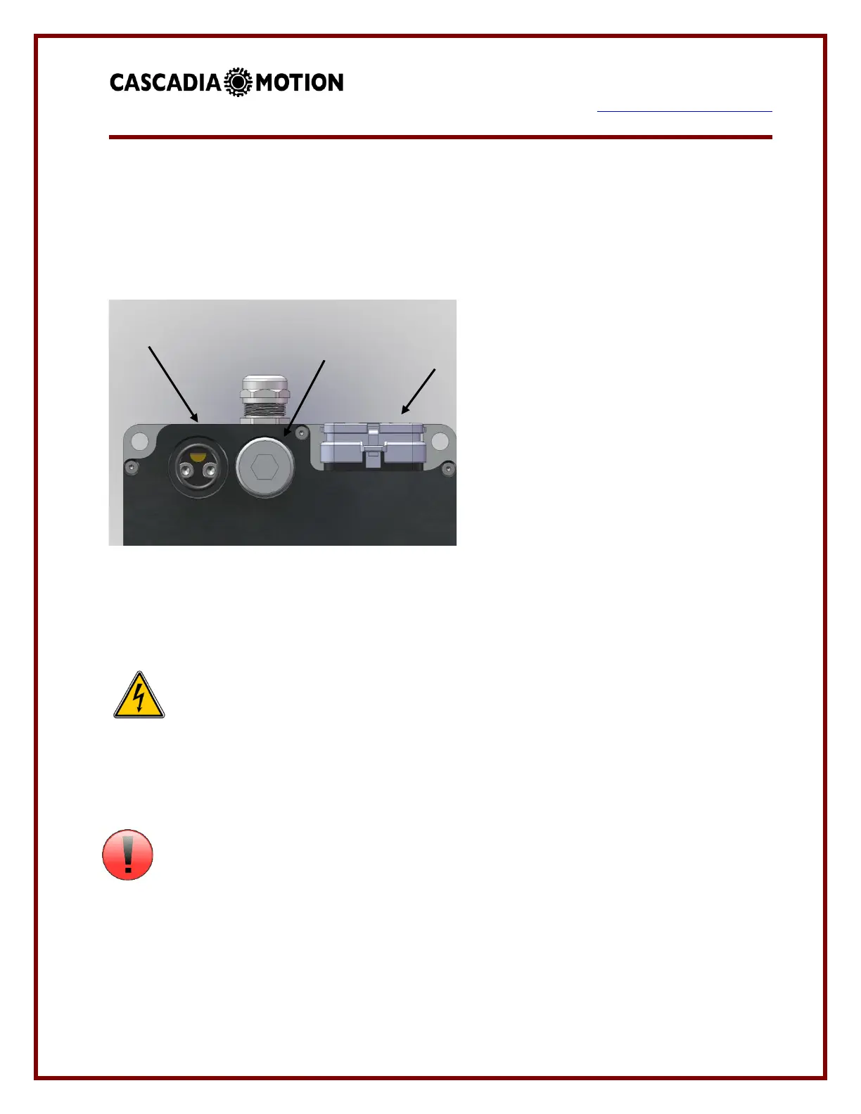
3.6.1 DC+ / DC-:
DC/Battery power is provided to the controller via two wire ports located at the rear of the
controller (PM100 and PM150 shown)
or front (PM250/RM100/RM300). The
DC power ports are marked clearly on
the front face of the
PM250/RM100/RM300 controllers. The
DC power must be run through an
external pre-charge circuit to safely
charge the capacitors inside the
controller before the main contactor
engages (refer to application schematic).
The main contactor provides a safety
disconnect of the DC power in case of a fault condition. Make sure that the wire to the drive
is sized properly to handle the current.
DANGER: Before changing the wiring make sure that the internal DC bus
capacitors are discharged. The voltage should be measured at the terminals before
disconnecting. If there is any doubt about the safety wait at least 1 hour after power has
been removed before touching the terminals.
ATTENTION
Refer to the PM100 HV Connection Manual for more information on how to install the wires
into the inverter.
On the PM250 unit the DC connections are marked “+” for the DC+ and “-“ for the DC-.
 Loading...