7929 SW Burns Way Phone: 503 344-5085
Suite F
Wilsonville, OR sales@cascadiamotion.com
1/14/2021 RMS PM Hardware User Manual 7 of 54
3.1 Liquid Cooling Connections:
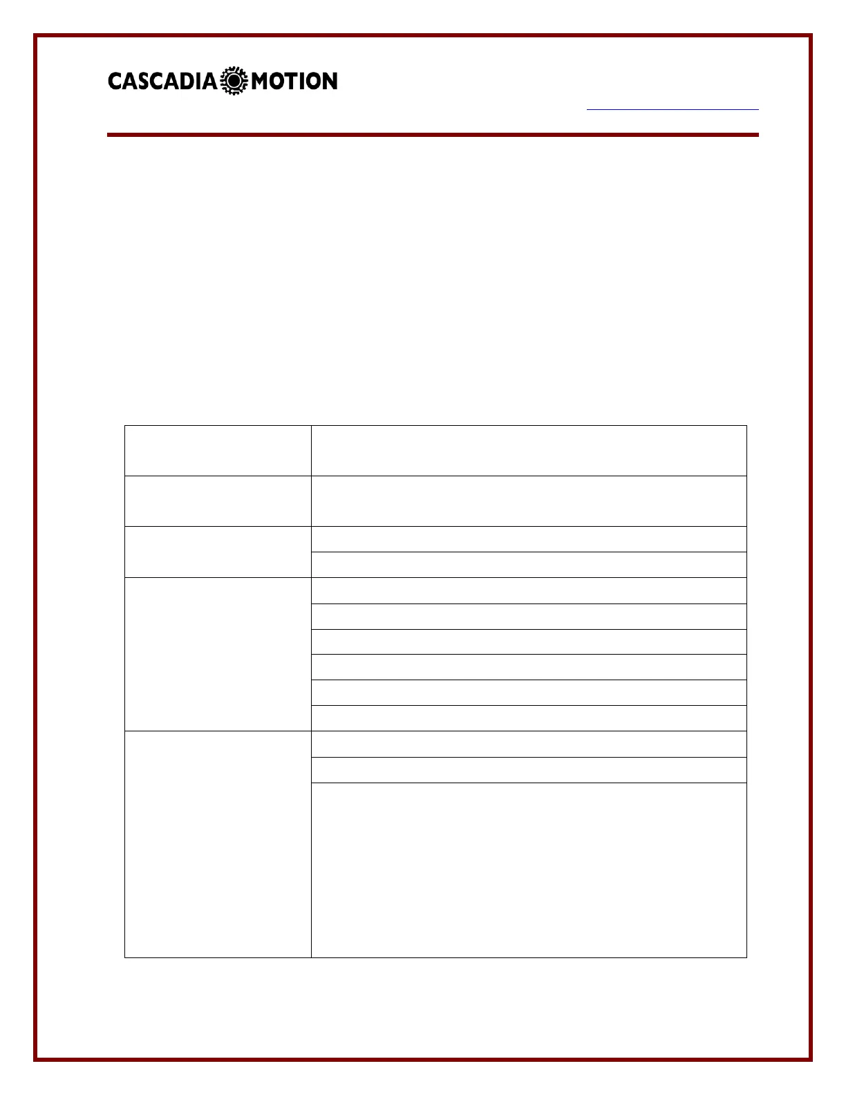
The controller must be cooled by passing liquid through it. The controller includes two ports
to be used for liquid cooling. The fluid direction for the PM250 inverter is marked into the
case of the inverter. The PM100 and PM150 has a more symmetrical design and is less
sensitive to fluid direction. However, it is preferred that the rearmost plenum (the ports
furthest from the 3 AC output terminals) be the fluid inlet, as this keeps the coolest fluid near
the DC Link capacitor assembly. The PM250 has markings on the housing that indicate the
required direction of the coolant through the inverter. See table below for coolant
specifications:
50/50 mix ethylene glycol (antifreeze) / water or propylene
glycol / water; with Aluminum corrosion inhibitor additive
-30°C to +80°C full power
Operation -40.. -30; +80.. +100°C with de-rated output
8 – 12 LPM (2 – 3 GPM), PM100/PM150/RM100/CM200
20 – 30 LPM (5 – 6 GPM), PM250, RM300
PM100, 0.3 bar (4.4 psi) @ 8 LPM @ 25°C
PM150, 0.4 bar (5.8 psi) @ 8 LPM @ 25°C
PM250, 0.9 bar (13 psi) @ 20 LPM @ 25°C
RM100, 0.06 bar (0.8 psi) @ 8 LPM @ 25°C
CM200, 0.2 bar (2.9 psi) @ 8 LPM @ 25°C
RM100, Custom O-ring port, the following options are provided
to be installed in the unit, each kit includes materials for both
ports.
- ARaymond NT100 / 16mm Straight, CM p/n G1-0023-01
- ARaymond NT100 / 16mm 45deg, CM p/n G1-0024-01
- ARaymond NT100 / 16mm 90deg, CM p/n G1-0025-01
- 16mm / 5/8” Hose Barb, CM p/n G1-0026-01
 Loading...