7929 SW Burns Way Phone: 503 344-5085
Suite F
Wilsonville, OR sales@cascadiamotion.com
1/14/2021 RMS PM Hardware User Manual 30 of 54
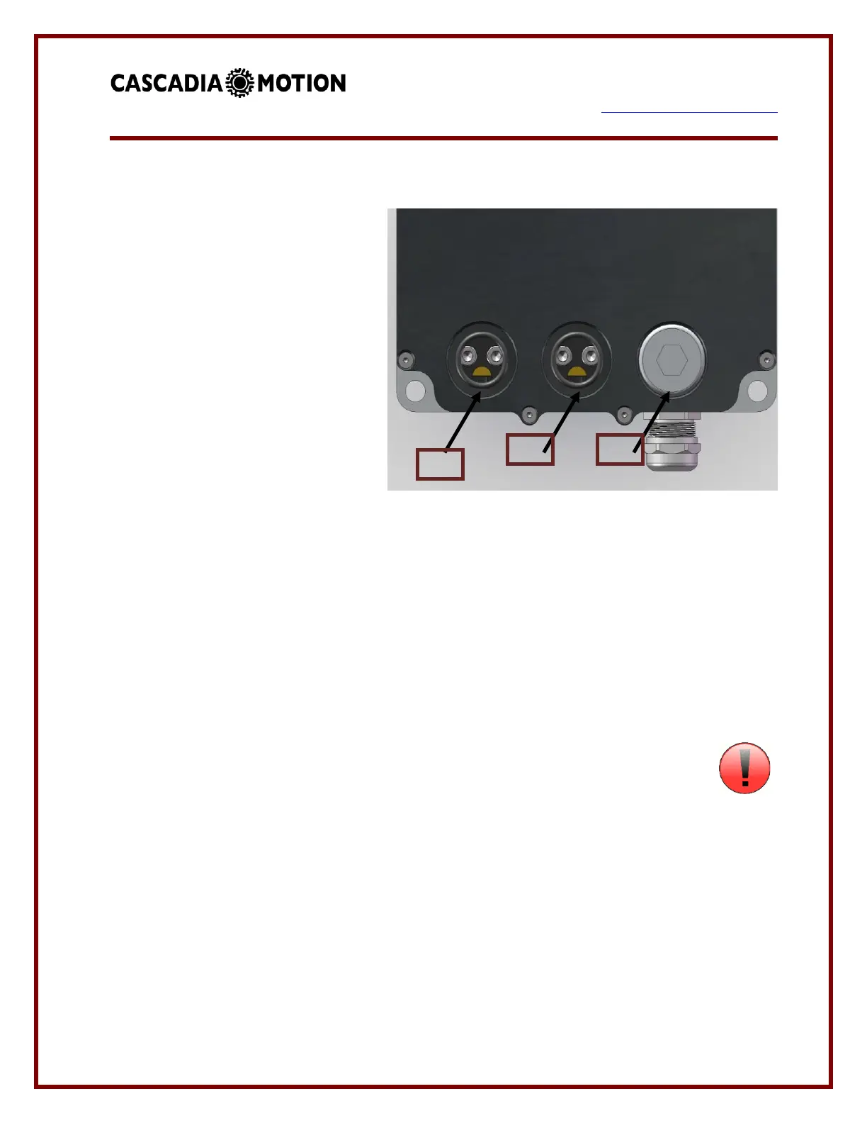
3.6.2 Phase A / Phase B / Phase C:
Phase A, Phase B, and Phase C are
wired to the motor. It is important the
3 wires be wired to the motor such
that they give the proper direction of
rotation. The motor wires are the
most likely to generate EMI and they
also carry a higher average current
than the DC power wires. When
installed in the vehicle these wires
should be kept as short as possible.
It is also recommended that
shielded wire be used for the motor
wires. This can be done by adding a copper braid over the wires, or using wire that includes
a shield. All of the PM100/150/250 family units are shipped with cable glands that are
metallic and designed to accommodate shielded wire.
The PM250 and RM300 AC motor connections are marked on the unit with the letters “A”,
“B”, and “C”. On the RM100 the phases are marked with “U”, “V”, and “W”.
The CM200 uses Rosenberger HPK connectors for the AC connections. The cables must
use shielded wire. The shield is connected to the chassis of the inverter and the chassis of
the motor.
3.6.3 Pre-Charge Circuit:
An external pre-charge circuit must be used with the controller. The circuit limits
peak inrush current into the controller when the main contactor is engaged. The pre-charge
circuit adds a resistor, relay, and fuse in parallel with the main contactor. When the controller
is powered on the controller will first engage the pre-charge relay to charge the capacitors
internal to the controller. If the capacitors charge properly then the main contactor will
engage.
The pre-charge resistor should be sized to rapidly charge the capacitor, but not dissipate too
much power in a fault condition. The pre-charge resistor should be sized so that if the
controller had a short on its input the pre-charge resistor would not fail. The pre-charge relay
 Loading...