7929 SW Burns Way Phone: 503 344-5085
Suite F
Wilsonville, OR sales@cascadiamotion.com
1/14/2021 RMS PM Hardware User Manual 43 of 54
Note: Only PM100/PM150 Connections shown, refer to PM250/RM100/RM300
connector descriptions for equivalent pins.
3.7.7 Encoder Interface (Not included on RM100/RM300):
The induction motor control software currently mandates the use of a position encoder on
the motor. The encoder provides information about motor speed that is used by the
induction motor control software. The controller provides a 5V interface to power the
external encoder and to receive, level translate, and filter the signals from A, B and INDEX
channels. For induction motor applications the INDEX channel is not used, but it may be
wired. The encoder is connected internally to the TI DSP QEP Module (Quadrature Encoder
Peripheral), which has special hardware for wide dynamic range speed and angle
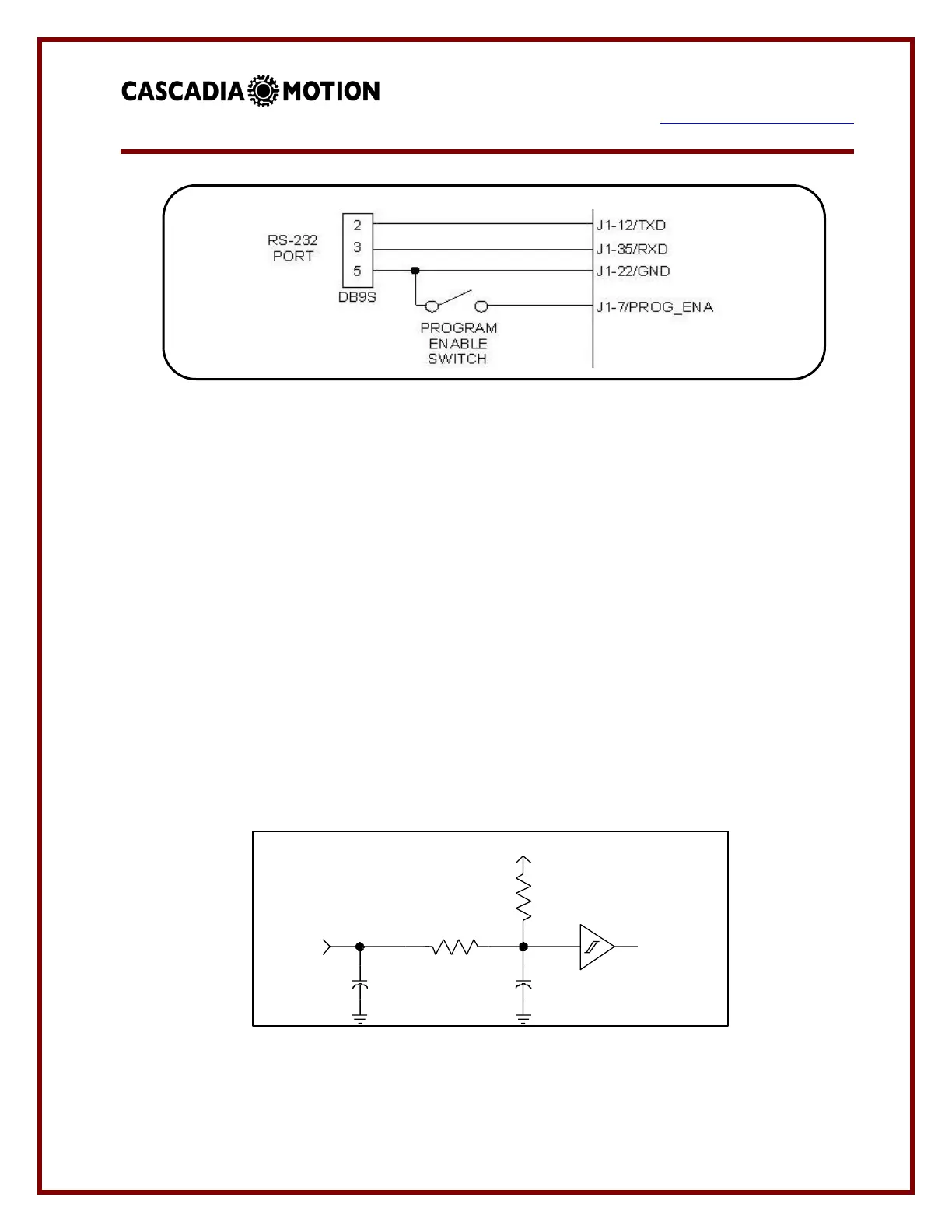
calculation from the encoder data. The drive has internal pull-up resistors on these inputs,
and works with encoders that have either bi-polar or open-collector outputs.
Schematic of Encoder Inputs
 Loading...