7929 SW Burns Way Phone: 503 344-5085
Suite F
Wilsonville, OR sales@cascadiamotion.com
1/14/2021 RMS PM Hardware User Manual 18 of 54
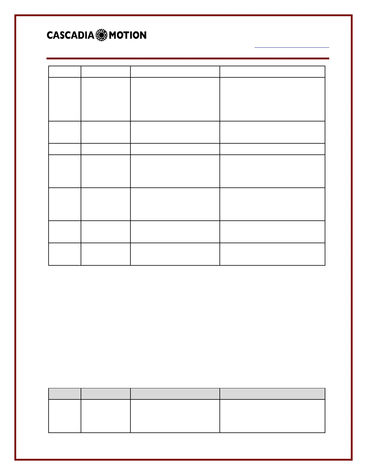
Resolver Cable Shield
connection
Resolver cable shield should
connected to this pin. Do not
connect the shield to the case of
the motor.
Resolver COS winding
return
Resolver SIN winding return
Temperature Sensor software
configurable for PT100 or
PT1000.
High Voltage Interlock Input
HVIL IN to HVIL OOUT is a circuit
loop that will read shorted when
all HV connectors are plugged in.
High Voltage Interlock
Output
Ground reference from analog
inputs.
3.5 RM300 Signal Connections
The RM300 uses two connectors for the low voltage I/O signals. The 35 pin connector
(marked I/O on the housing) is for the signals related to the communications/control of the
inverter. The 14 pin connector (marked M on the housing) is for the motor related signals.
The 35 pin mating connector is Tyco part number 776164-1, the 14 pin mating connector is
776273-1, mating contact is 770854-3 for 16-20 AWG wire. Must use Tyco crimper
58529-1 (AMP Pro-Crimper II). A kit of the connector and contacts is available from
Cascadia Motion as part number G1-0030-01.
“I/O” Connector – Input / Output Connector
Input power for inverter. Must be
on a switched connection as this
input will always draw current.
 Loading...