7929 SW Burns Way Phone: 503 344-5085
Suite F
Wilsonville, OR sales@cascadiamotion.com
1/14/2021 RMS PM Hardware User Manual 45 of 54
4. Vehicle Interface Setup
4.1 Analog Inputs:
There are 4 analog inputs on GEN 2 units (AIN1-4), 6 analog inputs on GEN 3 units
(PM100/PM150/PM250) as AIN1-6, and 3 analog inputs on the RM100 (AIN1-3) and 5
analog inputs on the RM300 (AIN 1-4 and AIN6). The CM200 has 4 analog inputs. The
inputs are intended for general analog signal sensing (0 – 5V). There are 5 dedicated RTD
sensor inputs (three 1,000 Ohm and two 100 Ohm calibrated RTD channels) on GEN 2 units.
There are 2 RTD inputs on GEN 3 units and RM100/RM300, selectable as PT 100 or
PT1000 by software.
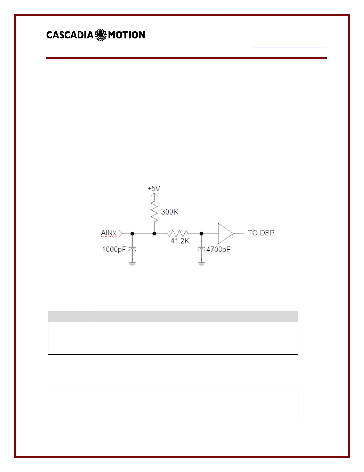
Schematic of Analog Inputs
The vehicle control system assigns the analog inputs as follows:
ACCEL
The input should be tied to the vehicle accelerator. The input can be
used with either a 0-5V signal or a potentiometer.
Motor thermistor
The motor thermistor can be connected between this input and
analog ground. An external pull-up resistor will be required.
BRAKE
The input should be tied to the brake pedal.
The input can be used with either a 0-5V signal or a potentiometer.
 Loading...