7929 SW Burns Way Phone: 503 344-5085
Suite F
Wilsonville, OR sales@cascadiamotion.com
1/14/2021 RMS PM Hardware User Manual 33 of 54
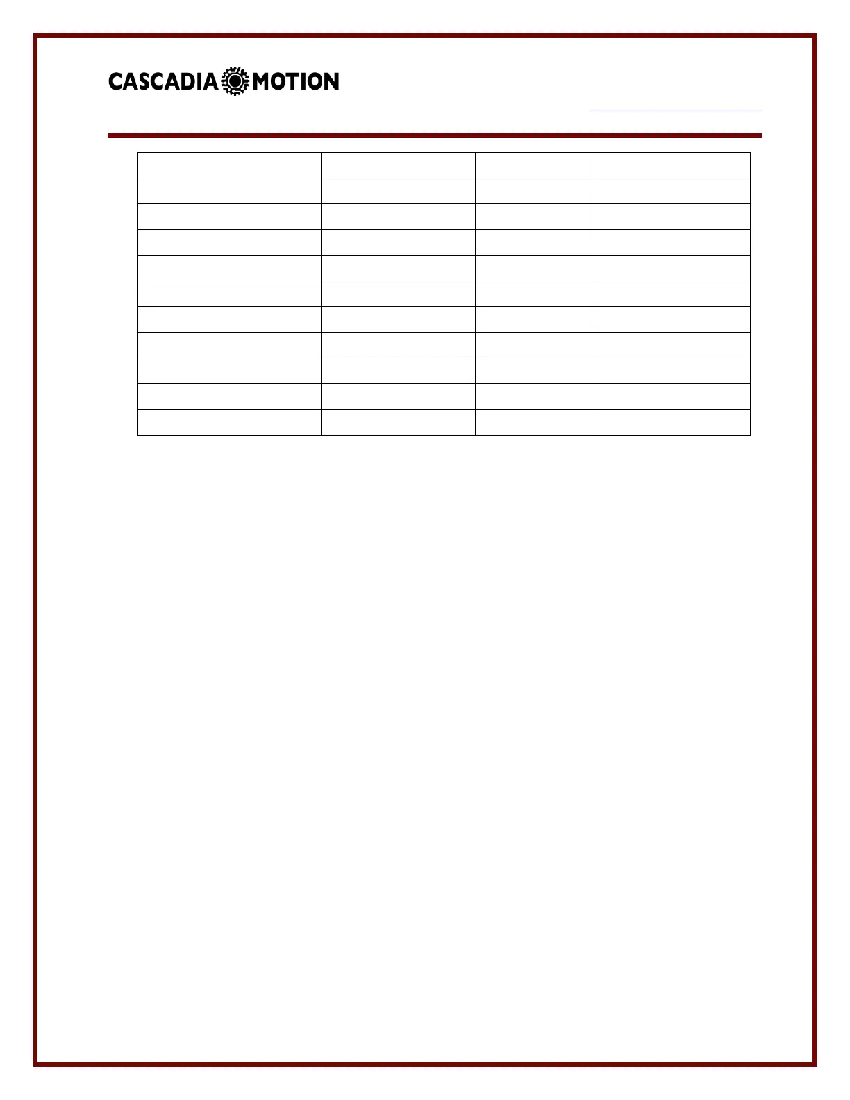
For reference the value of 3 time constants is shown. This time would dissipate the voltage
to less than 5% of the original value. Three time constants would allow the voltage to
decay to a value that is normally safe to touch. However, the capacitors will still have some
energy stored in them.
The passive resistance value shown in the table in connected to the high voltage DC bus at
all times. The inverter will draw a corresponding amount of current from the high voltage at
all times. For example if a PM100DX is being used at 320V it would draw 320/120K =
2.7mA even when the inverter is disabled.
If it is desired to have the DC bus voltage discharge faster the user must either provide an
external method of discharge or consider the use of the Active Discharge feature of the
inverter. Consultant the manual Inverter Discharge Process.
3.6.7 12V Power:
The inverter requires a source of 12V power to operate. Normally, this power will be on a
switched circuit. The inverter will turn on and communicate without high voltage present.
This allows setup of parameters without high voltage.
When the vehicle is turned OFF - the 12V power is removed from the controller by a switch.
This switched 12V power is connected to the BATT+ terminals (refer to pin list for pin
designation). The ground return for 12V power is connected to the GND terminals (refer to
 Loading...