EasyManuals Logo

Cascadia PM Series User Manual

Cascadia PM Series
54 pages
To Next Page IconTo Next Page
To Previous Page IconTo Previous Page
Page #27 background imageLoading...
Page #27 background image
7929 SW Burns Way Phone: 503 344-5085
Suite F
Wilsonville, OR sales@cascadiamotion.com
1/14/2021 RMS PM Hardware User Manual 27 of 54
Pin #
Pin Name
Description
Notes
L1
RLY1
High Side Driver
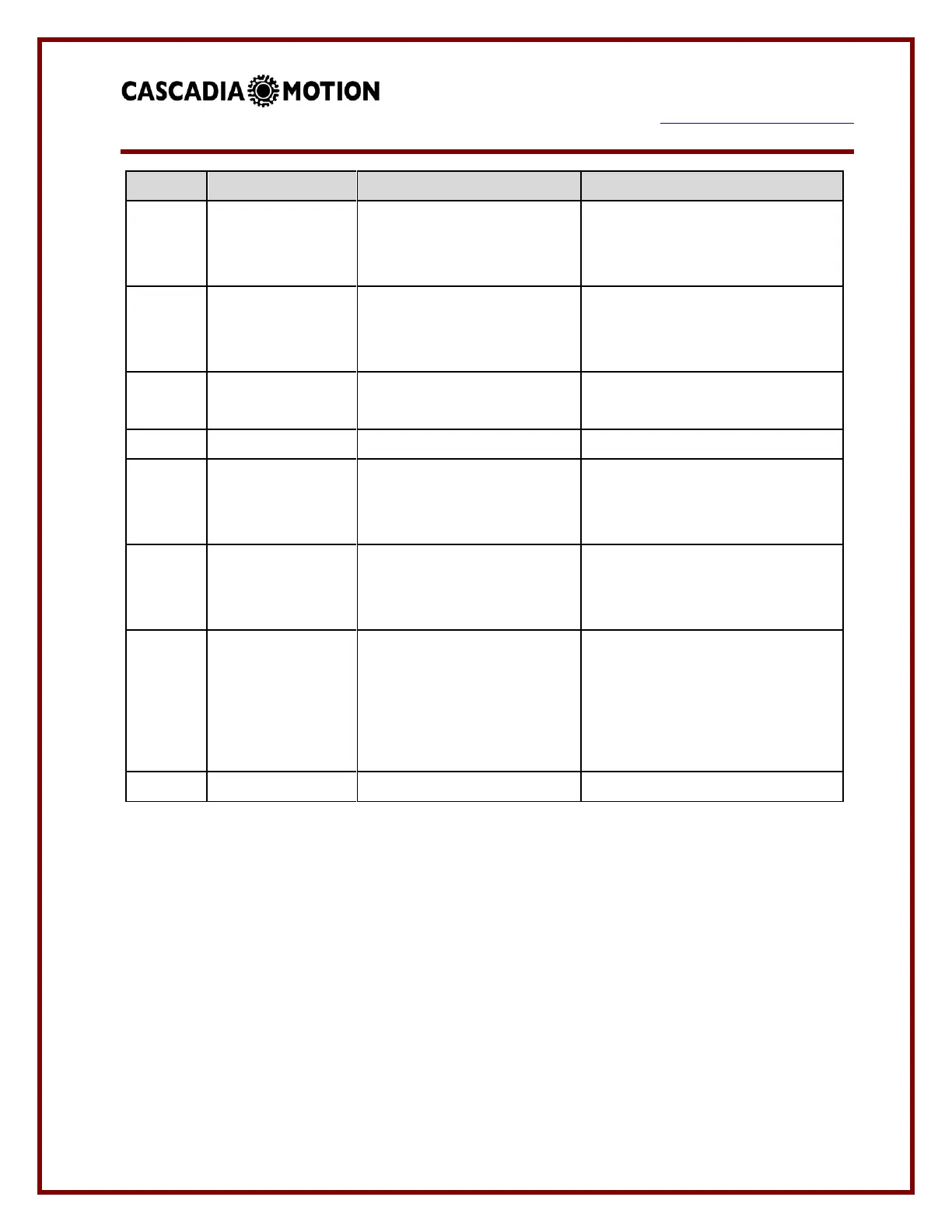
If pre-charge function is used
this output serves as the
pre-charge contactor output.
L2
RLY2 (Main)
High Side Driver
If the pre-charge function is
used this output serves as the
main contactor output.
L3
RLY3
Lo-Side Relay Driver
OK Indicator Drive / 12V Power
Relay Drive
L4
RLY4
Lo-Side Relay Driver
Fault Indicator Drive
M1
KL30_BATT
12V/24V Constant Voltage
Constant 12V power, when in
the off state input current is less
than 1mA
M2
KL15
Switched 12V/24V
Turns on internal power supplies
to power up the inverter and
start communications.
M3
KL15_EN
Safety Switched 12V/24V
If voltage is removed then
inverter will declare a hardware
gate fault, a completely
hardware based disable of the
PWM from the inverter.
M4
KL31_GND
12V/24V System Ground
12V/24V system return.

Questions and Answers:

Question and Answer IconNeed help?

Do you have a question about the Cascadia PM Series and is the answer not in the manual?

Cascadia PM Series Specifications

General IconGeneral
BrandCascadia
ModelPM Series
CategoryController
LanguageEnglish

Related product manuals