7929 SW Burns Way Phone: 503 344-5085
Suite F
Wilsonville, OR sales@cascadiamotion.com
1/14/2021 RMS PM Hardware User Manual 38 of 54
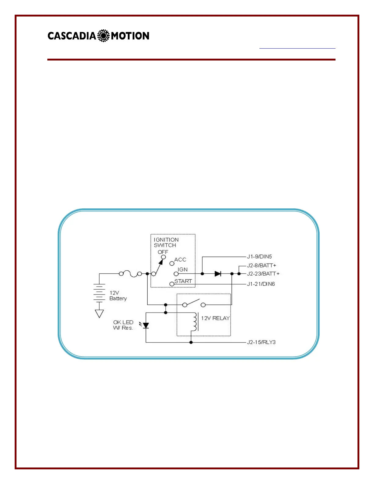
(b) Typical Ignition Configuration (PM Products Only)
In this configuration an external, user supplied relay, diode, and switch are used to
control power. When the Ignition Switch is put into the IGN position power is supplied
through the diode. Once the controller completes an initial power up sequence it then
turns on the RLY3 output to turn on the external 12V relay. The controller monitors
DIN5 to control the relay. When it is detected that Ignition has been removed (via DIN5)
an orderly shutdown process is initiated. When the process is completed the RLY3
output is turned off and power is removed from the controller. In this mode the START
position of the switch is used to actively turn on PWM to the motor (VSM mode).
The diode should have a current rating of at least 3 amps.
Note: Only PM100/PM150 Connections shown, refer to PM250 connector for
equivalent pins.
 Loading...