7929 SW Burns Way Phone: 503 344-5085
Suite F
Wilsonville, OR sales@cascadiamotion.com
1/14/2021 RMS PM Hardware User Manual 51 of 54
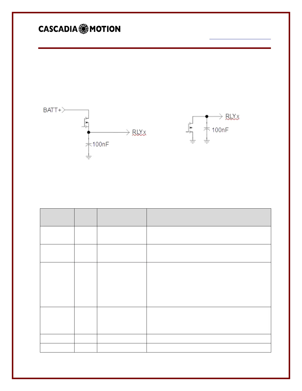
4.3 Digital Outputs
There are up to 6 digital outputs available. See the table below for more specifics on
availability across each model. There are two types of outputs available depending on the
particular model.
Schematic of High-Side Driver Schematic of Low-Side Driver
The vehicle control system assigns the outputs as follows:
This output provides power to the pre-charge
relay.
This output provides power to the main contactor.
This output provides a grounded signal to the OK
indicator. The indicator turns on when power is
applied to the drive and the drive has completed
the pre-charge sequence. If used, this output is
also used to power the external 12V power relay.
This output provides a grounded signal to a fault
indicator. The indicator will blink a fault code if the
drive has detected a fault.
Not assigned. Available for use through CAN.
Not assigned. Available for use through CAN.
 Loading...