V-R200 Installation Manual
– 5 –
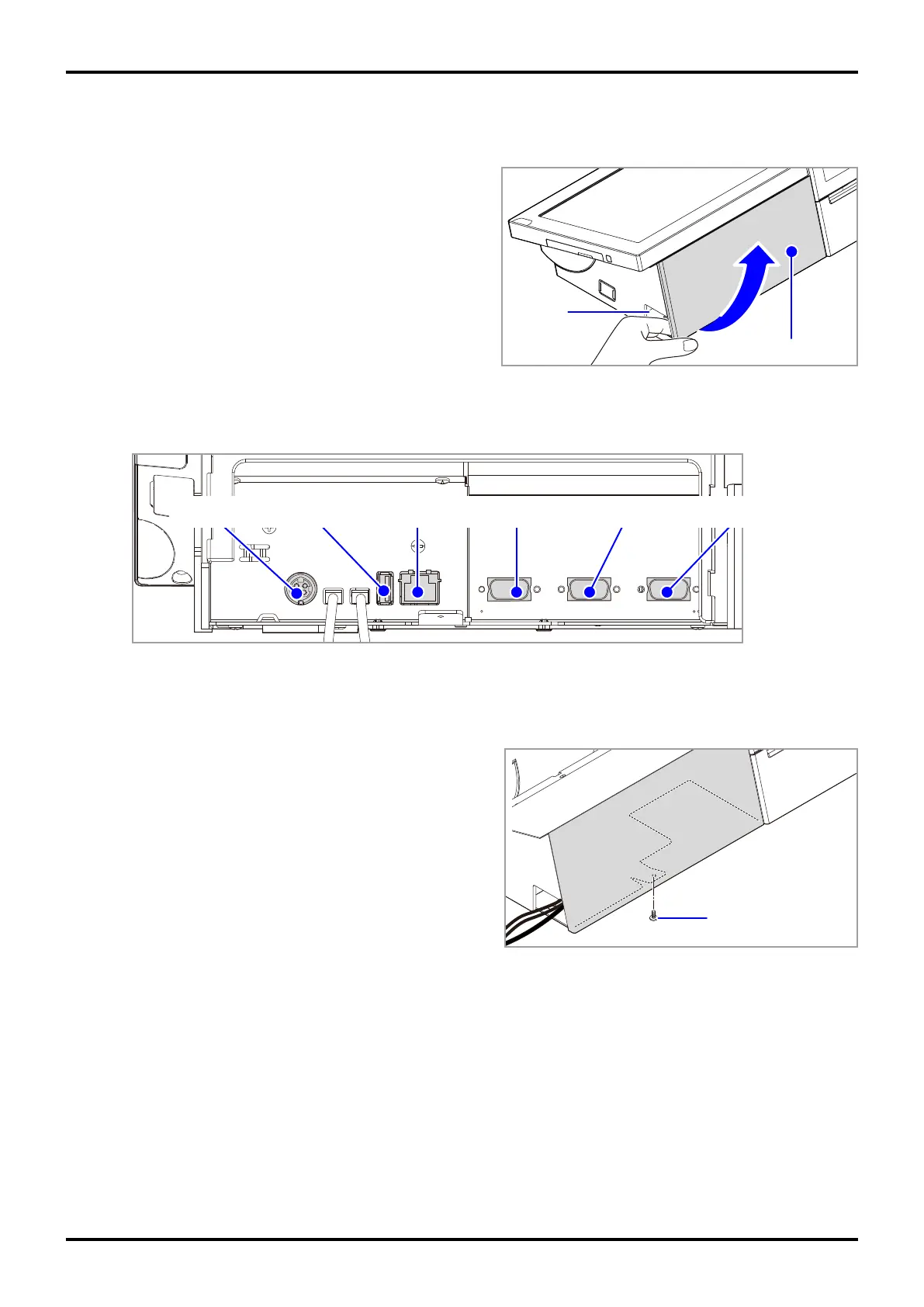
2. Connecting cables
(1) Remove the connector cover.
Cutout
Connector cover
Fig. 4
(2) Connect necessary cables.
DC jack
USB port LAN port COM3 port COM2 port COM1 port
Fig. 5
(3) Run the cables from the side of the product as shown in Fig. 6, and attach the connector cover by
fastening the included connector cover fastening screw.
Connector cover
fastening screw
Fig. 6
 Loading...