17
System Installation
8.4. Scroll to the “Power” section and select “Line Voltage.”
• 60 Hz - select 208 V or 230 V
• 50 Hz - select 200 V, 220 V, or 240 V
8.5. Select “Ok” and the “Save” icon in the upper right corner of the screen.
9. Install the ber optic probe and enter the GF number as outlined below.
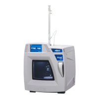
9.1. Install the Fiber Optic Probe.
9.1.1. Remove the plug from the temperature sensor.
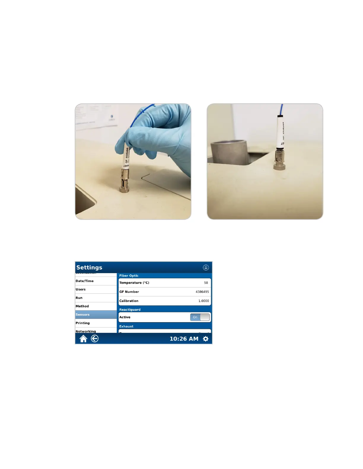
9.1.2. Insert the sensor into the ber optic port located on top of the MARS 6. The sensor is attached
to the module with a locking “collar” on the sensor. Push the collar in, twist it clockwise, and then
release it to lock the sensor into the module.
9.2. Enter the GF number.
9.2.1. Select the System Menu icon in the bottom right corner of the screen.
9.2.2. Select Settings.
9.2.3. Select Sensors.
9.2.4. Select the current GF number.
9.2.5. Using the Keyboard, enter the GF number of the Fiber Optic Probe installed in the instrument. The
GF number can be found on the white connector on the probe.