SILENT 610/620/150 INSTALLATION
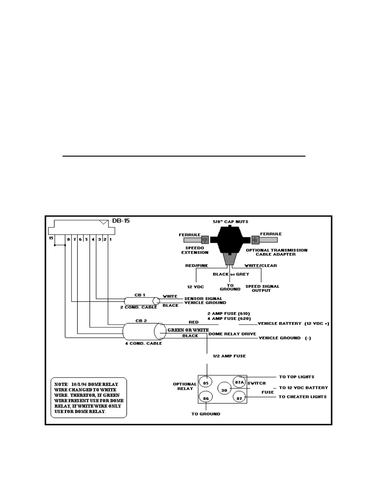
Black wire, CB 1 - Connect to black wire of Centrodyne transducer. For electronic vehicle speed sensors,
connect this wire to vehicle ground (-).(Notes:1 & 2)
White wire, CB 1 - Connect to white wire of Centrodyne transducer. For electronic vehicle speed sensors,
connect this wire to the speed signal output of the sensor.(Notes:1 & 2)
Black wire, CB 2 - Connect to vehicle ground (-).
Red wire, CB 2 - Connect using a 2 amp (SILENT 610) or 4 amp (SILENT 620) in-line fuse to +12 volts at
the fuse box or directly to the positive (+) post at the battery.
Green or White wire, CB 2 - SEE NOTE IN DIAGRAM BELOW. If relay option employed, connect to post 85
using a ½ amp fuse to allow meter to drive dome/top light relay. Connect post 86 to ground, post 30 via
switch and fuse to +12 volts battery, post 87A to dome or top lights, and post 87 to cheater lights if required.
ENSURE LOCATION OF METER DOES NOT INTERFERE WITH AIR BAG DEPLOYMENT
Note 1. Ensure the taximeter internal speed signal jumper has been selected properly, i.e., select electronic for vehicle
speed sensors (usually magnetic) that provide an analog or varying amplitude signal (low amplitude), and select
mechanical for Centrodyne transducers or sensors that provide a digital, on/off, high/low type signal. See page
13 for Speed Signal Jumper Selection.
Note 2. When using a Centrodyne transducer (part # Y014-1) connect ground and signal wires as per above, and
connect the red or pink wire to vehicle +12 volts (meter does not supply transducer power).
NOTE: 10/1/96 Dome Relay
Wire changed to White Wire.
Therefore, if Green Wire
present use for Dome Relay, i
White Wire Only use for Dome
Relay
12