EasyManua.ls Logo

Cerlic BB2 - User Manual

Cerlic BB2
24 pages
Print Icon
To Next Page IconTo Next Page
Loading...
2002-11-18 MANE11/02 VER2.00
BB2 Control Box
BB2 is the control box to which most Cerlic sensors can be connected. The
measured signal is converted to a linearized 4-20mA output signal. The BB2 allows
the user to easily adjust settings and serves as a display for the measured output. The
unit also includes communication protocols for connection to various input systems.
Question and Answer IconNeed help?

Do you have a question about the Cerlic BB2 and is the answer not in the manual?

Summary

4. Working Principle

5. Installation and Start-up

8. Wiring Connections

9. Jumper Settings

Analog Outputs

Explains the jumper settings for configuring the two analog outputs, including sourcing and sinking modes.

Digital Inputs

Details jumper configurations for digital inputs, their use in selecting calibration curves, and activation methods.

10. Relay Outputs

12. Connection of Automatic Flushing

13. Operational Interface

Changing Values in the Menus

Details how to change values and selections within the BB2 menus using the arrow and ENTER keys.

14. Menus for the BB2 Control Box

Setup Menu Options

Covers setup parameters such as Language, System units, Date, Time, and display Contrast for the BB2 control box.

Format and Fieldbus Settings

Details menu options for setting data formats (Temp, Date, Time) and configuring Fieldbus communication parameters.
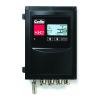
15. Getting Started

16. Technical Specification for BB2 Control Box

APPENDIX 1, Instructions for EMC

APPENDIX 2, Connection of Shielded Cable to Fitting

APPENDIX 3, Shielded Cable Without Fitting

APPENDIX 4, Extending Shielded Cable

Cerlic BB2 Specifications

General IconGeneral
BrandCerlic
ModelBB2
CategoryControl Unit
LanguageEnglish