- 7 -
configured in the sensor menu, and the box will prevent two sensors from using the
same output. We suggest using a shielded twisted pair AWG20 (0.5mm
2
) cable to
connect the BB2 box to another system. If both outputs are connected to the same
system a double twisted pair cable may be used. Make sure the shield is properly
grounded according to good EMC practice.
The two relay outputs may be configured to be used for alarm or cleaning. The cable
type required depend on the use, and selected voltage. Make sure the relays are jumped
for the correct voltage, and that the maximum ratings of the outputs are not exceeded.
Chart for relay jumpers is attached to the inside of the front door.
Three digital inputs are used to select calibration curves for consistency or suspended
solids sensors from a remote location. They are activated by applying +24 VDC, and
have a common ground. We suggest the use of a 4-lead AWG20 (0.5mm
2
) cable.
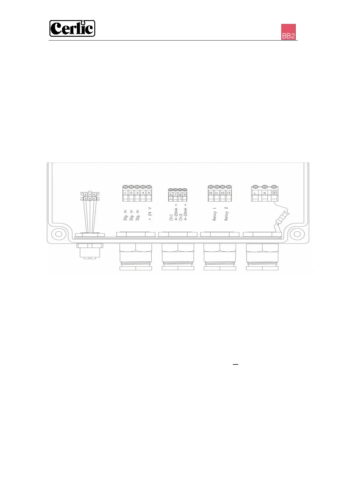
Figure 2 1 2 3 4 5
1. One sensor, or two sensors with Y-splitter, plug- and twist connection
2. Digital inputs (terminals 1 – 5)
3. 4-20mA outputs (terminals 6 – 9). Selected in each sensor set-up menu.
(Please refer to the sensor manual)
4. Relays (terminals 10 – 13)
5. Power (terminals L (load or power), N (neutral) and ⊥ (ground)
NOTE! Start-up of the instrument takes place as soon as power is supplied although it
may take up to 30 seconds before the sensor has been identified. When the instrument
starts, then type of sensor and version is shown in the screen window for ten seconds.
When more than two sensors are connected to the BB2 control box, a Field Bus
communication module must be installed in the BB2 control box to transfer the
measuring results to a SCADA or DCS system.