22
The basic installation is complete.
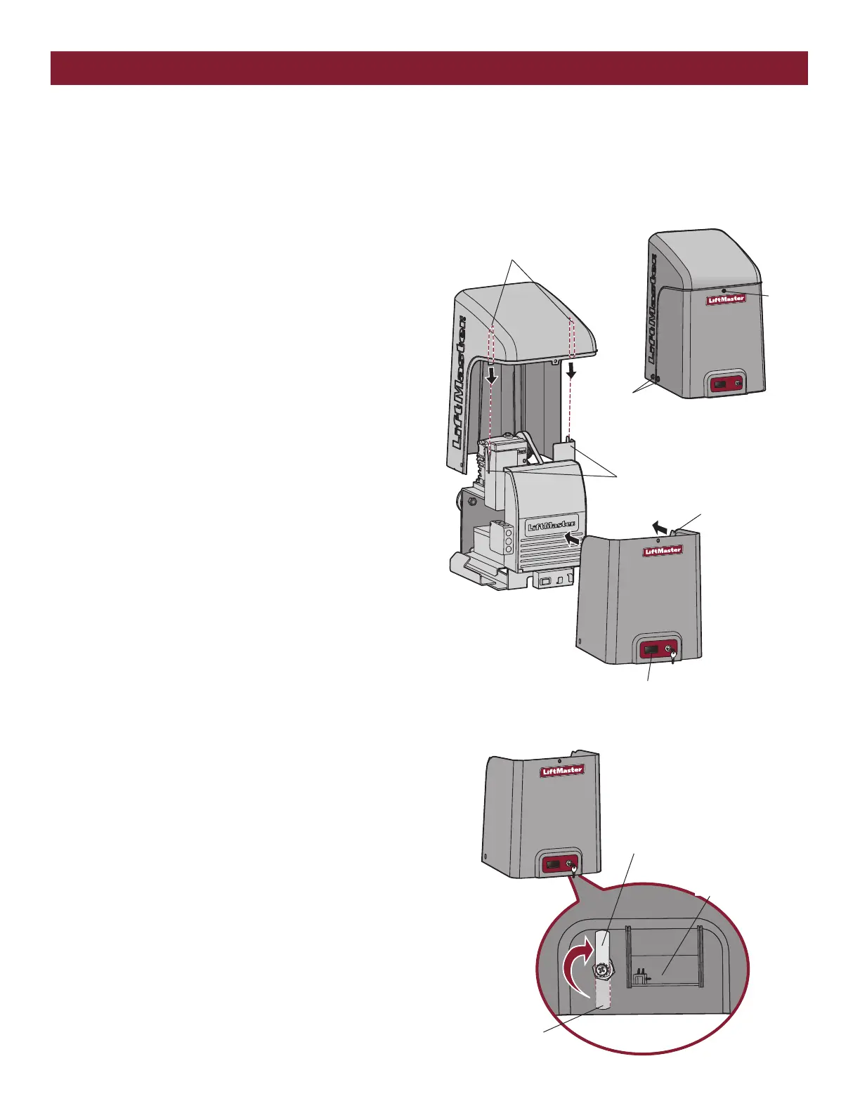
1. Align the tabs on the rear cover with the slots on the chassis and
place the cover over the operator.
2. Secure both sides of the rear cover to the chassis with two 5/16-18
lead in screws.
3. Align the front cover with the back cover, making sure the grooves
line up.
4. Secure the front cover to the chassis with two 5/16-18 lead in screws.
5. Secure the front cover to the rear cover using the 5/16-18 lead in
screw.
TO LOCK THE ACCESS DOOR
From the factory the access door for the reset switch will not be locked.
To lock the access door follow the steps below:
1. Locate the lock tab on the back of the front cover and remove the
screw securing the tab to the cover.
2. Turn the tab 180 degrees, then secure with the screw. The access
door can now be locked.
Tabs on Rear Cover
Slots on Chassis
Groove on Front Cover
5/16-18 Lead
In Screws
5/16-18
Lead In
Screw
Access Door
Lock Tab
Factory Default position
(back of front cover)
Access Door
STEP 9
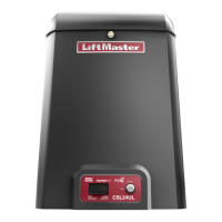
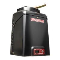
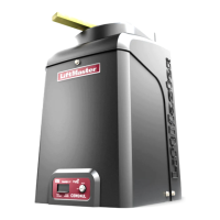
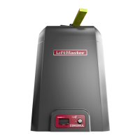
INSTALL THE COVER
The operator cover consists of two pieces: a rear cover and a front cover. The front cover can easily be removed to access the electrical box. To access
the reset switch slide the access door up. The front cover and access door can be locked with the key.
INSTALLATION