49
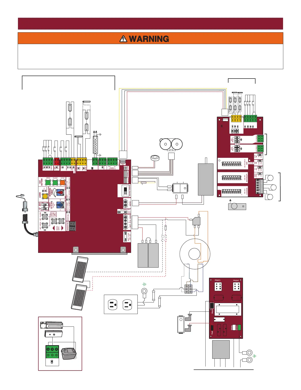
AC & BATT FAIL
BACKDRIVE
COM
LINK
BA
SHADOW INTERUPT EXIT
SBC
OPN
CLS
STP
COM
EYE
ONLY
EYE/
EDGE
EYE/
EDGE
COM
1
2
3
OPEN
CLOSE
TO MAIN
BOARD
POWER
+
-
-
-
+
-
+
LOCK
N.O.
COM
N.C.
+
-
+
-
+
+
-
+
-
+
-
+
-
+
-
+
-
Coaxial Antenna Cable
L
N
GND
N
GND
Heater
Two 12V Solar Panels in Series
Accessory
Power
Outlets
12V 7AH Battery
12V 7AH Battery
Transformer 375 VA, 24V, 120V
Bridge Rectifier
EXPANSION BOARD
Primary/Secondary link
to other gate operator
Shielded
Twisted
Pair Cable
Butt Splice
Switch/5A Breaker
Input Power Connection
EMI FILTER/SURGE PROTECTION BOARD
Ground the shield of the
cable to the chassis ground
of each operator.
Yellow
Blue
Black
Black
Black
Install male insulated faston
connectors on solar panel leads.
Plug them into the female faston connectors that
were connected to the bridge rectifier.
Purple
Brown
Blue
Gray
Orange
Orange
Red
Red
Red
L
Black
Red
Black
White
CONTROL BOARD
Piezo Alarm
APS Encoder
1/2 HP 24 Vdc Motor
Product ID
White
White
Black
Red
Black
Yellow
Red
Run
Stop/Reset
Reset Switch
To Pin 1
To Pin 2
To Pin 6
To Pin 5
Black
Red
Field Wiring
NOTE: The accessory outlet is
disabled and cannot be used
with the 240 Vac option.
Blocking Diode
Maglock
(Optional)
(not provided)
Antenna
Photoelectric Sensors
Field Wiring
Edge
Edge
Photoelectric Sensors
Field Wiring
EDGE OR EYE
EDGE OR EYE
EYE
Field Wiring
Wire Loop
Wire Loop
Wire Loop
Loop
Detector
N.C.
N.C.
EXIT: Soft Open (used for exit probe,
telephone entry, external exit loop detector,
or any device that would command the
gate to open)
OPEN and COM: Hard Open (line-of-sight)
CLOSE and COM: Hard Close (line-of-sight)
STOP and COM: Hard Stop (line-of-sight)
To protect against fire and electrocution:
• DISCONNECT power (AC or solar and battery) BEFORE installing or
servicing operator.
For continued protection against fire:
• Replace ONLY with fuse of same type and rating.
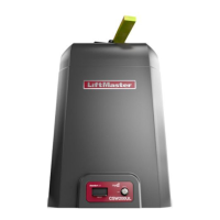
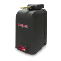
WIRING DIAGRAM