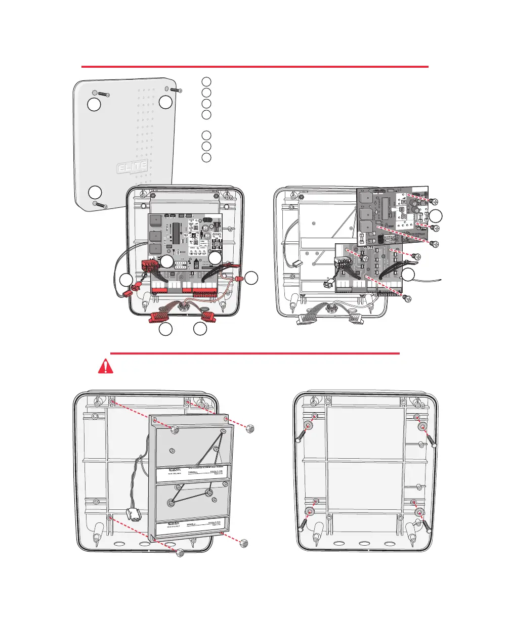
REMOVING THE CONTROL / SURGE BOARDS
MOUNTING THE CONTROL BOX
Remove the four nuts and remove battery rack.
Reverse this process to reinstall.
Mount control box with four screws and washers
(recommend #10 thru 1/4-20 Bolts or Screws)
Do Not over tighten.
Caution: Do Not make new mounting holes, or enlarge existing holes in control box.
Use the four mounting holes provided.
BLACK
MOTOR
WHITE
RED
BRAKE
SINGLE OR MASTER ONLY SLAVE ONLY
BROWN
BLUE
LIMITS
GREEN
BLACK
MOTOR
WHITE
RED
BRAKE
BROWN
BLUE
LIMITS
GREEN
CENTER
LOOP
+24 VAC
INPUT
SAFETY
LOOP
EXIT
LOOP
BURGLAR
ALARM
INPUT
GROUND
RADIO
+24 VOLT
UL SENSOR
LAKE FOREST, CALIFORNIA
www.eliteaccess.com
REV A
MIRACLE SURGE PROTECTION
1 2 3 4 5 6 7 8 9101112 13141516 1718192021222324252627
®
8
BLACK
MOTOR
WHITE
RED
BRAKE
SINGLE OR MASTER ONLY SLAVE ONLY
BROWN
BLUE
LIMITS
GREEN
BLACK
MOTOR
WHITE
RED
BRAKE
BROWN
BLUE
LIMITS
GREEN
CENTER
LOOP
+24 VAC
INPUT
SAFETY
LOOP
EXIT
LOOP
BURGLAR
ALARM
INPUT
GROUND
RADIO
+24 VOLT
UL SENSOR
LAKE FOREST, CALIFORNIA
www.eliteaccess.com
REV A
MIRACLE SURGE PROTECTION
1 2 3 4 5 6 7 8 9 101112 13141516 1718192021222324252627
®
Unscrew the 4 Phillips head screws from the cover.
Unplug the J1 and J3 plugs.
Unplug battery connector.
Unplug all accessory wires from Surge Suppressor's removable
terminals.
Disconnect ground wire.
Remove three Phillips screws f
rom control board and remove board.
Remove three Phillips screws from surge suppressor board and
remove board.
P
O
W
E
R
C
H
A
R
G
E
O
K
B
A
T
T
E
R
Y
L
O
W
®
ACCESS SYSTEMS INCAC
C
E
SS SYS T
E
M
S I
N
C
M
A
G
L
O
C
K
R
E
P
L
A
C
E
F
U
S
E
W
H
E
N
L
E
D
I
S
O
N
R
E
V
E
R
S
E
S
E
N
S
O
R
SYSTEM
ON
A
L
A
R
M
A
L
A
R
M
S
E
N
S
O
R
O
P
E
N
I
N
S
I
D
E
OFF
N
O
YES
ON
T
I
M
E
R
C
E
N
T
R
A
L
S
T
R
IK
E
O
P
E
N
S
A
F
E
T
Y
L
O
O
P
R
A
D
IO
R
E
C
C
E
N
T
E
R
L
O
O
P
C
O
N
T
R
O
L
6
0
3
S
T
O
P
B
Y
P
O
S
I
T
I
V
E
S
T
O
P
O
P
E
N
O
U
T
S
I
D
E
1
1
1
1
2
2
2
3
3
5
5
4
4
6
6
7
7
4
15