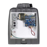
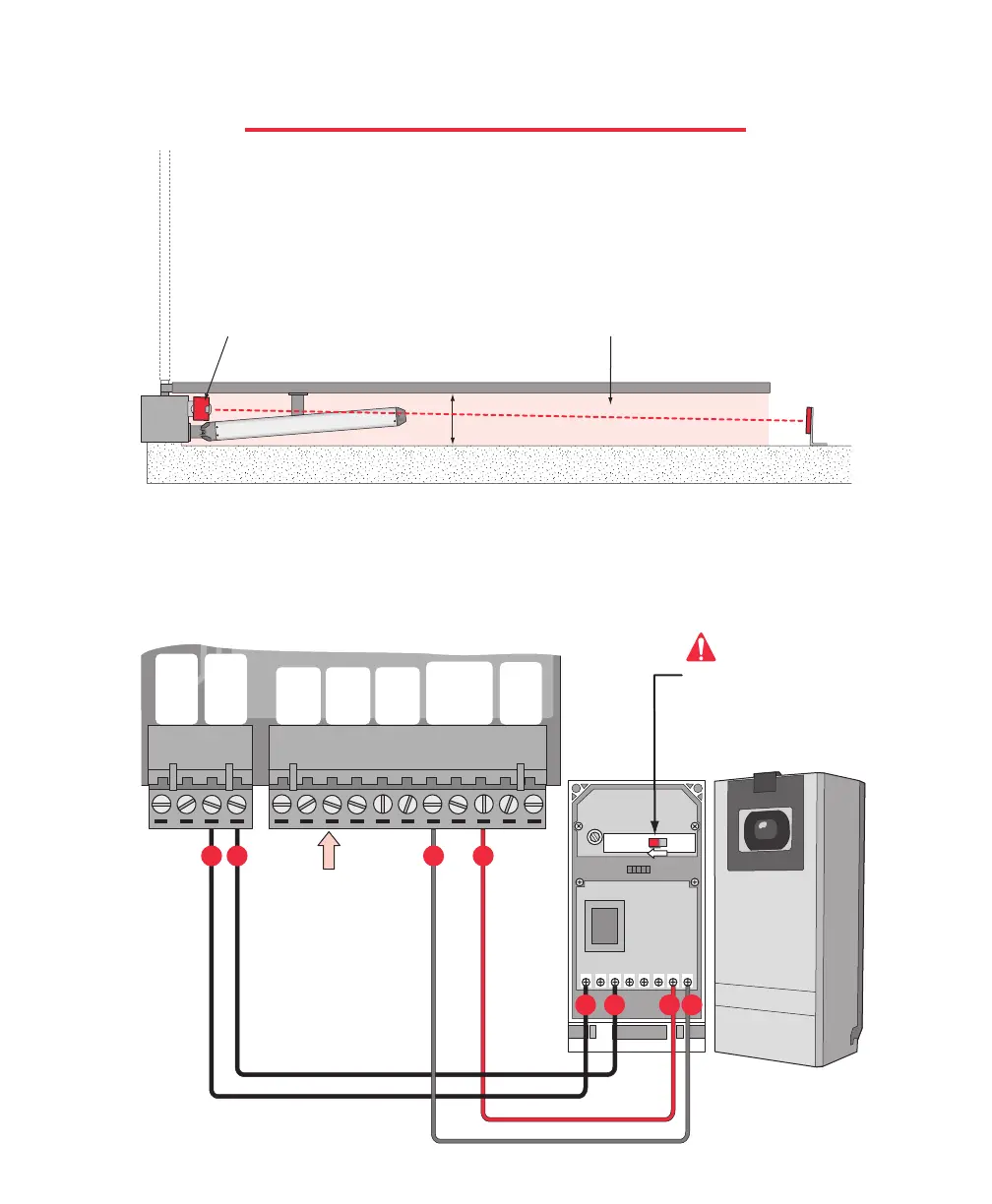
PHOTOCELL INSTALLATION
Black 22 AWG
Black 16 AWG
Black 16 AWG
Red 22 AWG
To reduce the risk of injury, You must install a photocell sensor when the gate opens to less than 18”
from a wall or any other object or potential entrapment installation. Follow the installation instructions
provided with the photocell sensor for accurate placement of the photocell and the reflector.
Elite Part #
A OMRON
If multiple sensors are being used, all of the photo beam sensors are to be connected in parallel at the UL
sensor input on the surge suppression board.
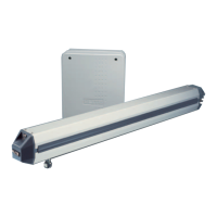
If you are going to use a non-contact sensor as a secondary entrapment protection you should use a recognized
component to comply with the revised UL 325 intended to be used in class I or class II gate operator, like the
following: OMRON Retro-Reflective Photocell, Model: E3K-R10K4-NR
13
2456
24V to
240VDC
(NC1)(C1)
LIGHT ONLIGHT ON
DARK ON
This switch must be in the
"Light On" pos ition or
photocell will not function
correctly.
Potential Entrapment
Area (Shaded)
Gate in Open Position
Gate in Closed Position
Photocell
Less than 18"
Reflector
and
Bracket
Important!
CENTER
LOOP
+24 VAC
INPUT
SAFETY
LOOP
STRIKE
INPUT
BURGLAR
ALARM
INPUT
GROUND
RADIO
+24 VOLT
UL SENSOR
13 14 15 16 17 18 19 20 21 22 23 24 25 26 27
23 251615
Back
Front
25
1615
Removable
Terminal
Connectors
23
26