8
ASSEMBLY STEP 1
Assemble the Rail & Install the Trolley
To avoid installation diffi culties, do not run the garage
door opener until instructed to do so.
To prevent INJURY from pinching, keep hands and
fi ngers away from the joints while assembling the rail.
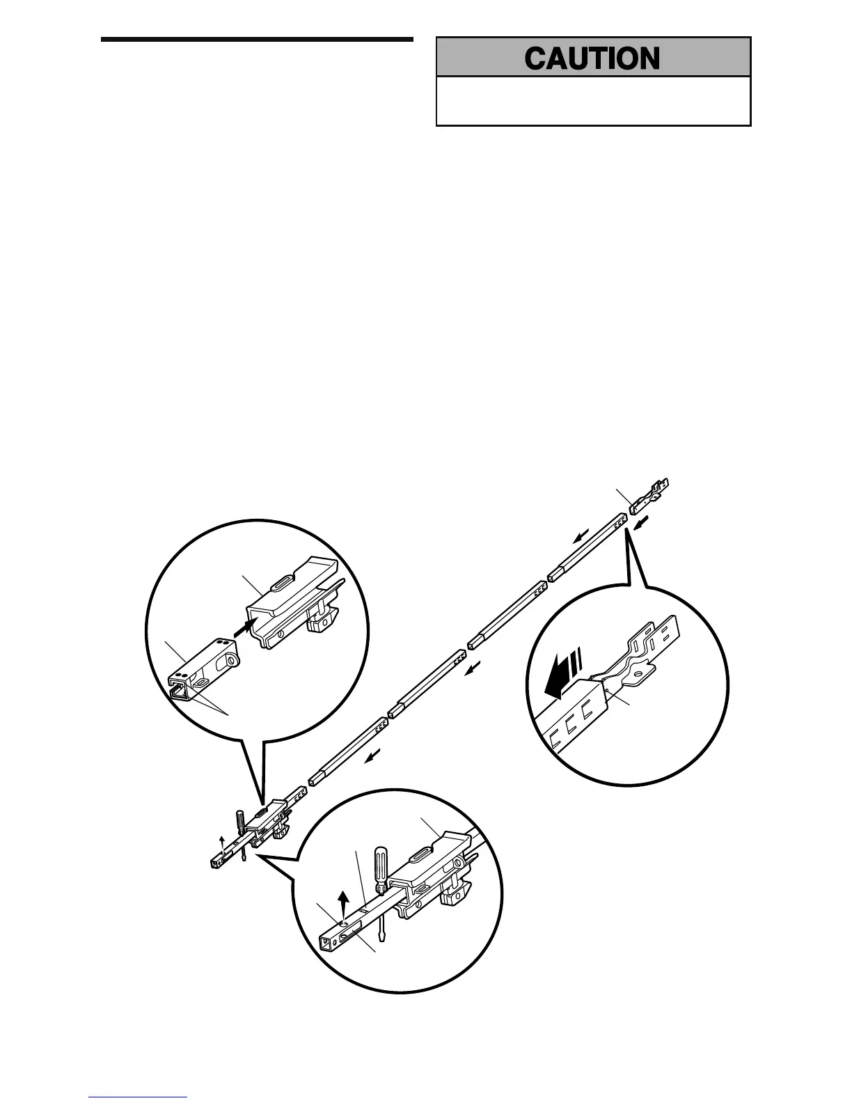
The front rail has a cut out “window” at the door end.
The front and back rail both have rail tabs. These rail tabs
MUST be on top of the rail when assembled.
1. Remove the straight door arm and hanging bracket
packaged inside the front rail and set aside for
Installation Step 5 and 12. NOTE: To prevent INJURY
while unpacking the rail carefully remove the straight
door arm stored within the rail section.
2. Align the rail sections on a fl at surface as shown and
slide the tapered ends into the larger ones. Tabs along
the side will lock into place.
3. Place the motor unit on packing material to protect
the cover, and rest the back end of the rail on top. For
convenience, put a support under the front end of the
rail.
4. As a temporary trolley stop, insert a screwdriver into
the hole 10" (25 cm) away from the front of the rail, as
shown.
5. Check to be sure there are 4 plastic wear pads inside
the inner trolley. If they became loose during shipping,
check all packing material. Snap them back into
position as shown.
6. Slide the trolley assembly along the rail from the back
end to the screwdriver.
7. Slide the rail onto the “U” bracket, until it reaches all
the stops on the top and sides of the “U” bracket.
Trolley
Rail
Tab
Front Rail Section
(TO DOOR)
Outer Trolley
Wear Pads
“U” Bracket
Inner Trolley
Idler
Pulley
Hole
SLIDE TO STOPS
ON TOP AND
SIDES OF “U”
BRACKET
Window Cut-Out
Back Rail Section
(TO MOTOR UNIT)