19
POWER
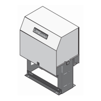
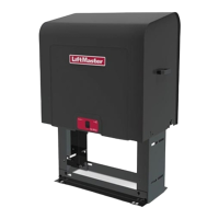
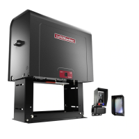
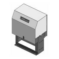
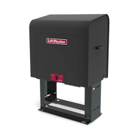
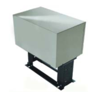
MODELS CSW200U AND SL3000U
COMM
LINK
BA
ANTENNA
CURRENT
SENSOR
MOTOR DRIVE
RPM & LIMITS
ALARM
EXP.
BOARD
24 VAC IN
CLASS 2 SUPPLY
24 VAC
500 mA MAX
ID RESET
GND
BIPART
DELAY
2
4
6
8
HANDING
OPEN
LEFT
OPEN
RIGHT
MOTOR
ID
J14
MOTOR RED MOTOR BLUE
J11
J7 SWITCH
TRANSFORMER
J5
J3
COMM
120VAC
MOTOR
WHITE
J2
J1
INPUT
NEUTRAL
OUTLET
J12
J6
BLACK
WHITE
INPUT
HOT
J4
J10
MOTOR
CONTROL
CURRENT
SENSOR
J8
J16
SWITCH
J17 J20
J13
J19 J21
J18
COM
120
240
COM
120
240
24 V c.a.24 V c.a.
CONTROL BOARD
TRANSFORMER
Orange
Orange
POWER BOARD
SINGLE PHASE
Black
JUNCTION BOX
INCOMING POWER
White
AC POWER SWITCH
Green
Yellow
Gray
HOT
NEUTRAL
GROUND
*
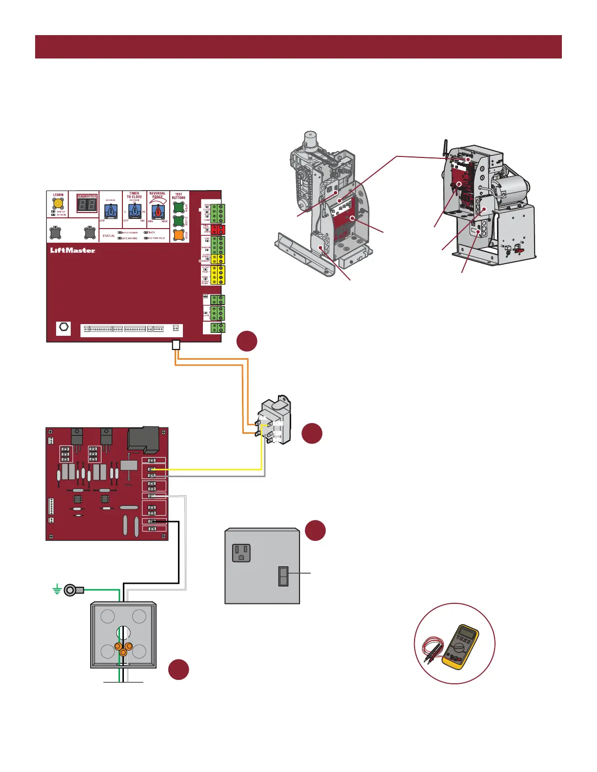
1 Check the incoming power.*
Check breaker first, then check wiring coming
into operator. The voltage should be 120 Vac.
2
Check the AC power switch.
Is it ON?
Check the power board.*
Check the gray and yellow transformer
wires on the power board. The voltage
should be 120 Vac. If not, replace the
power board.
3
Check the transfomer and control board.*
Check the orange 24 VAC IN wires at the control board.
The voltage should be about 21-28 Vac.
If the voltage is NOT 21-28 Vac, replace the transformer.
If the voltage is 21-28 Vac, replace the control board.
4
CONTROL BOARD
MODEL CSW200U
POWER BOARD
(located behind control board)
MODEL SL3000U
JUNCTION BOX
AC POWER SWITCH
AC POWER SWITCH
JUNCTION BOX