5
BASIC TROUBLESHOOTING
RELAYS
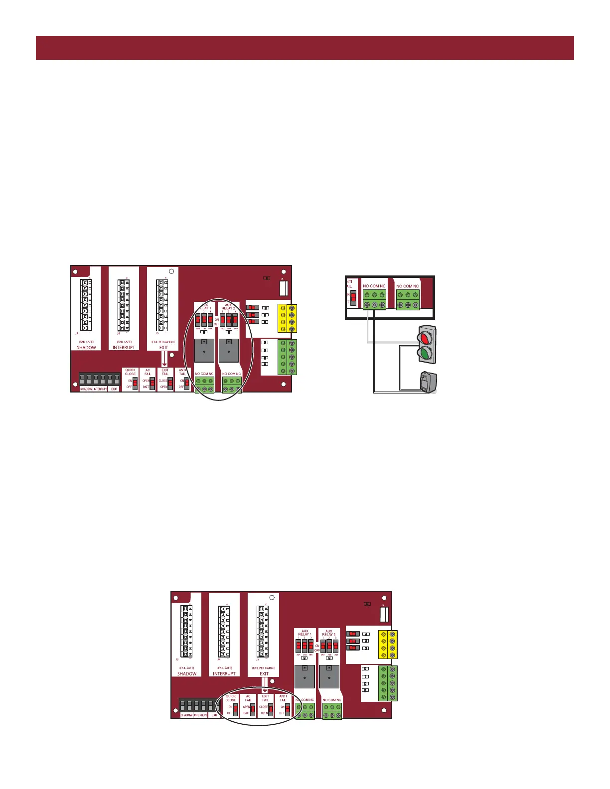
EXPANSION BOARD RELAYS
In gate operators, relays are often used to either control certain operator functions or activate/deactivate ancillary devices such as heaters or lights.
When electricity is applied to a relay coil, it energizes a magnet and will close a Normally Open switch or open a Normally Closed switch. A relay
typically has prongs labeled COMM , NO, NC, and two prongs to power the relay coil. Relays are available with different coil voltages and contact
options. LiftMaster’s line of gate operators primarily use double pole/double throw relays. The auxiliary relays are single pole, double throw. A pole is
another name for a switch. Double pole is two separate switches being turned on or off by the same activation coil (two separate Comms, NCs and
NOs). Double throw means there are two positions for the output (NO and NC).
The 2 Auxiliary Relays on the expansion board can be set to activate in different conditions based on how you set the 3 switches for each relay. They
can be set to activate any time the gate is open or closed or when the gate is in motion. In one setting you can trip the relay 3 seconds before the gate
begins to move and while the gate is in motion. You can set the relay to activate if the gate is forced off the closed limit position. One setting for Aux
Relay 1 uses the LEDs for the Open, Close, and Stop inputs to display how many cycles (to the nearest 1000) the operator has performed. The
Auxiliary relays can also be used in conjunction with a barrier arm operator for the SAMS or tandem function.
EXPANSION BOARD SWITCH SETTINGS
• The Quick Close feature allows the gate to close without having to travel to the full open position. When active, the operator monitors the Interrupt
Loop and Close Eyes inputs and once the vehicle clears these devices the gate will reverse and Close.
• When the AC Fail Open switch is selected, the operator will move the gate to the Open position if AC Power is lost. If the switch is set for the
Battery option, the operator will run on the battery until the battery drops below a certain voltage. At that point, the gate will either open or close
depending on how you set the Low Battery switch on the main control board. NOTE: The AC Fail Open switch is not functional for AC operators.
• The Exit Fail switch sets the operator to either open or remain closed in the event of an internal detector failure (loop short or open).
• The Anti-Tailgate switch alters the way the Interrupt Loop affects gate operation. When the switch is on, the gate pauses if the gate is closing and
the interrupt loop is activated. The gate will stay paused until the vehicles backs off the loop, then continue closing.
SBC
OPN
CLS
STP
COM
EYE
ONLY
EYE/
EDGE
EYE/
EDGE
COM
1
2
3
OPEN
CLOSE
TO MAIN
BOARD
POWER
SBC
OPN
CLS
STP
COM
EYE
ONLY
EYE/
EDGE
EYE/
EDGE
COM
1
2
3
OPEN
CLOSE
TO MAIN
BOARD
POWER
RELAY WIRING EXAMPLE
RELAYS ON THE EXPANSION BOARD
+
–
Traffic Light
Class 2 Power Source
(42 Vdc [34 Vac], 5 A maximum)