12
. The quantities common to the three
phases (phase shift of the phase-to-earth
voltage with respect to the phase-to-earth
current, PF, DPF, and tangent).
2. Validate using
(this validation is mandatory
for application of the parameter). The return
to the Configuration menu is immediate.
4.8 Current sensor
Automatically displays the type of current sensor
connected to the current sensing probe input
(Figure 37).
SUCR
Figure 10: The Current sensor menu.
The possibilities are:
MN93 clip: 200 A.
MN93A clip: 100A or 5 A.
C193 clip: 1000 A.
AmpFLEX A193: 3000 A.
PAC93 clip: 1000 A.
5A three-phase adapter.
Attention: if a 5A MN93A clip sensor or an Adapter
is used, the parameterising is as follows:
1. Definition of the transformation ratio.
- For a 5A clip, press
to parameterise the
primary current (1 A to 2,999 A) / secondary
current (1 A or 5 A) transformation ratio. Use
to select the fields and
to select the
values. Proceed in the same way for the
primary current and the secondary current.
- Adapter: press
to parameterise the current
primary (1 A to 2,999 A) / current secondary
(1 A or 5 A) transformation ratio. Use
to
select the fields and
to select the values.
Proceed in the same way for the primary
current and the secondary current.
2. Validate with
(this validation is mandatory
for application of the parameter).
3. Return to the Configuration menu by
pressing the key.
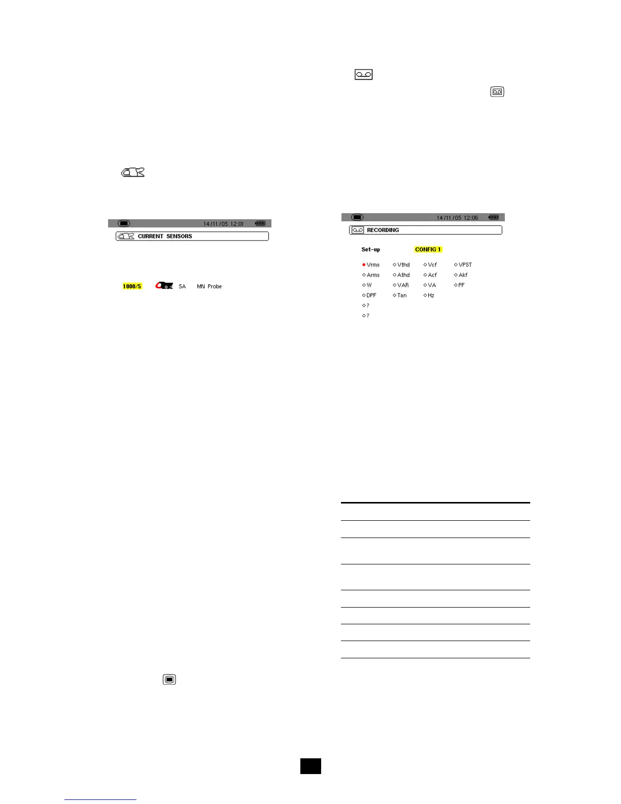
4.9 Recording
The C.A 8230 has a recording function - key -
(chapter 10, page 29) for digital recording of
measured and calculated values (Hz, Vrms, Vthd,
Athd, etc.). Since not all values are necessarily of
interest for a given recording campaign, those it is
more particularly desired to supervise are selected
in this recording parameterising menu. Four
independent configurations can be parameterised in
this way, each corresponding to a specific need of
the user, who when the time comes can simply
select the desired configuration in the list of four
configurations parameterised here.
SUEN
Figure 11: In this example, only measurements concerning
Vrms will be recorded.
1. The CONFIG1 zone is highlighted in yellow.
2. To define CONFIG1, go directly to point 3.
To define configurations CONFIG2, CONFIG3 or
CONFIG4, press and use the key to select
the desired configuration number. Press again
to validate.
3. Use the
and
keys to select each item
of information to be recorded in the
configuration currently being defined by
pressing
(the selection is then marked with
a red spot).
The values that can be recorded are:
Unit Designation
Vrms
RMS voltage (phase-to-phase 3φ).
Vthd Total harmonic distortion of the voltage
(phase-to-phase 3φ).
Vcf Peak factor of the voltage (phase-to-
phase 3φ).
VPST Short-term flicker.
Arms RMS current.
Athd Total harmonic distortion of the current.
Acf Peak factor of the current.
Table continued on page 13.

 Loading...