17
(table continued from page 16)
4. Column of current-related values.
RMS: RMS value calculated over 1 second (the
RMS value of the current is true - with DC
component - only with a PAC sensor).
THD: level of total harmonic distortion (also
called THD-F).
CF: peak factor calculated on the waveform
displayed.
DC: DC component of the current, with PAC
sensor only.
KF: K factor. Gives an indication of the sum of
the current harmonics and can help in choosing
a transformer.
DF: distortion factor (also called THD-R).
5. Current date and time.
6. Battery charge level.
5.5 Phase rotation
This sub-menu determines the phase order of a
three-phase network in three steps. The order of the
phases can be determined in either the single-
phase or the balanced three-phase connection
mode.
5.5.1 Step 1
1. Connect the 2 voltage measurement cables to
inputs Com and + of the C.A 8230 and place the
contact tips on the phases assumed to be L1
and L2.
2. The screen displays the procedure ...
RO01
Figure 22: Step 1 of Phase rotation.
... press the key.
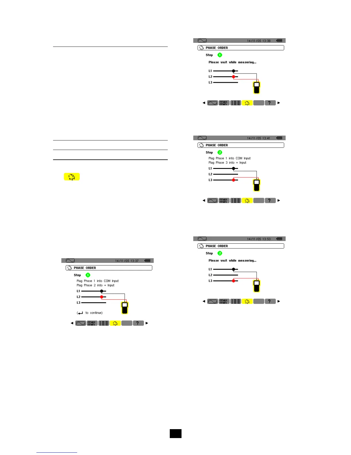
3. The screen indicates that the measurement is in
progress.
RO02
Figure 23: The screen during the measurement.
5.5.2 Step 2
The screen displays step 2 ...
RO03
Figure 24: Step 2 of Phase rotation.
... place the red contact tip on the phase assumed
to be L3. Do not press any other key; wait for the
result of the measurement as indicated in step 3.
RO04
Figure 25: The measurement is in progress.
5.5.3 Step 3
The screen indicates the order of the phases.
Reverse sequence is displayed
The phase assumed to be L3 leads the phase
assumed to be L2, which itself leads the phase
assumed to be L1.

 Loading...