37
11.3 Placing the cords
Insert the cords as follows:
002
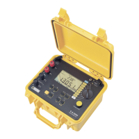
Figure 68: The connectors on the top.
Item Function
1. External power supply by specific mains power
unit.
2. 4-point input for current sensor (MN clip, C clip,
AmpFLEX, etc.).
3. Safety socket of the voltage measurement cable
(negative terminal).
4. Safety socket of the voltage measurement cable
(positive terminal).
Connect the measurement cords to the C.A 8230 as
follows:
Voltage measurement: COM and (+) terminals.
Current measurement: 4-point connector (item
2). On the current sensor, do not forget to set
the switch (if there is one) to a sensitivity that
corresponds to the current to be measured.
The measurement cords are connected to the circuit
to be studied as shown by the following diagrams.
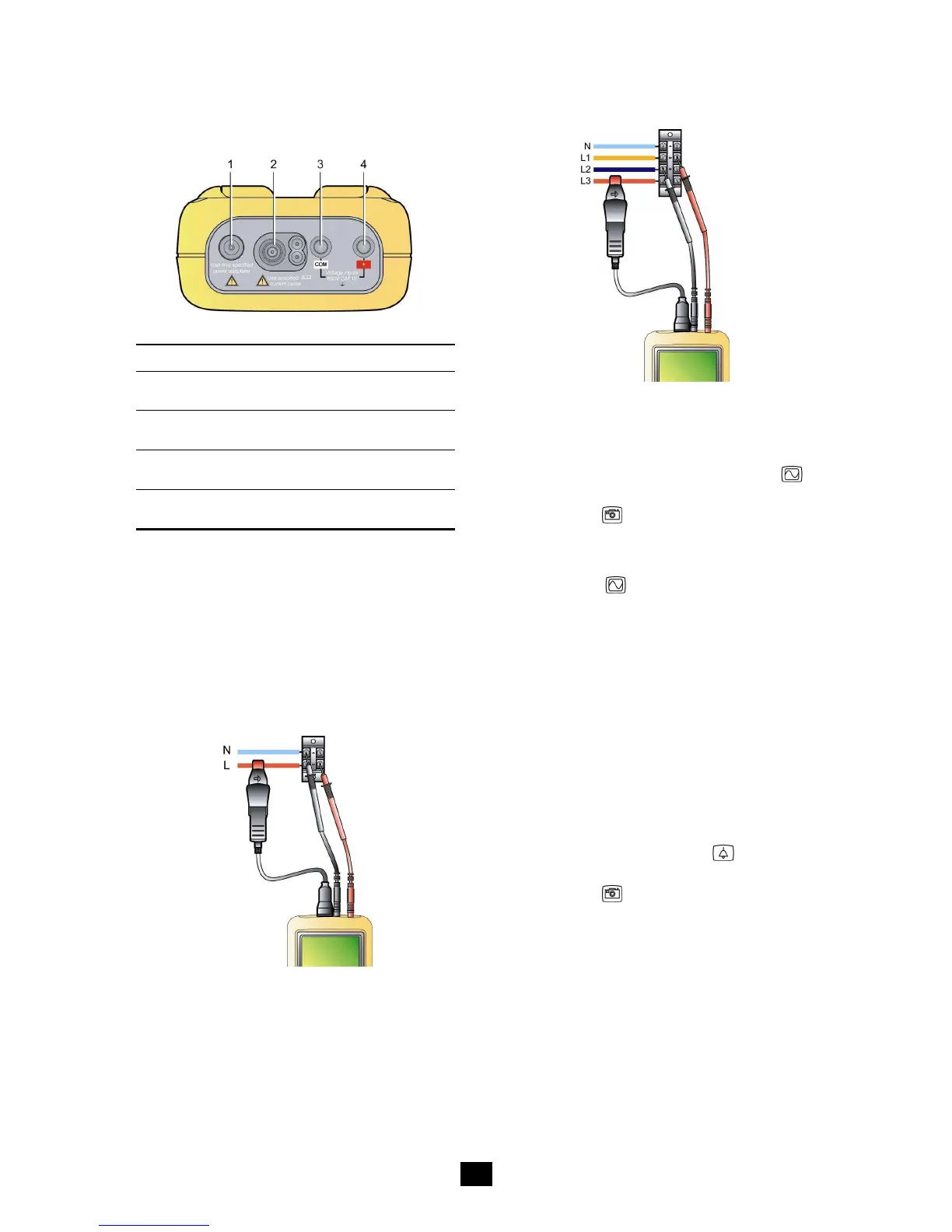
11.3.1 Single-phase network
Figure 69: Single-phase connection. 005
11.3.2 Balanced three-phase network
Figure 70: Balanced three-phase connection 006
Note: the neutral may or may not be present.
11.4 Measurement of waveforms
Reminder: any screen can be saved (screen grab)
by pressing the
key. Refer to chapter 8, page
25.
With the C.A 8230 switched on and connected to
the network (voltage and current measurement
cords), press the
key.
11.4.1 Display of waveforms
Refer to § 5.2, page 15.
11.4.2 Display of min., max., peak
Refer to § 5.3, page 16.
11.4.3 Display of all measurements
To display all voltage and current measurements
(RMS, DC, THD, CF, PST, KF, DF), refer to § 5.4,
page 16.
11.4.4 Display of phase order
Refer to § 5.5, page 17.
11.5 Detection of alarms
Reminder: any screen can be saved (screen grab)
by pressing the
key
. Refer to chapter 8, page
25.
11.5.1 Configuration
Configure the values to be supervised as explained
in § 4.10, page 13.
11.5.2 Starting
Use the function as explained in § 9.2, page 27.
11.5.3 Automatic stop
The alarm recording campaign is stopped
automatically at the Ending date and time
programmed by the operator.

 Loading...