CAC Gasoline Engine Maintenance And Servicing Manual
99
3.circuit illustration
1.injection/ignition system ECU 17.injection system warning light (on the instrument
panel)
2.battery 20.fuel cut-off switch
3.ignition switch 21.A/C control unit
4.25A system fuse 22.A/C compressor relay
5.5A ECU fuse 23.A/C compressor
6.dual relays 26.engine idling actuator
7.revolution counter 27.throttle valve position sensor
8. ignition coil 1(cylinder 1、4) 28.main ground wire of engine
9. ignition coil 2(cylinder 2、3) 29.absolute pressure sensor10. fuel vapor
recirculation solenoid 30.water temperature sensor
11.λsensor 31.intake air temperature sensor
12.electric fuel pump 32.ground wire for ECU block shield
13.main ground wire of engine 33.speed/ TDC sensor
14. fuel injector 34.CHECK—UP1 diagnosis socket
15.30A A/C fan fuse 35.A/C fan relay
16.7.5AA/C fuse U front cable junction box
ECU I/0 function
1. primary signal for ignition coil
2.B phrase idling actuator signal
3.D phrase idling actuator signal
4.protect relay signal
5.without connection line
6.warning light energizing signal
7.without connection line
8.A/C input signal (see note)
9.without connection line
10.diagnosis socket L connection line
11.tacho sensor negative input
12.λsensor negative input
13.water temperature sensor negative
input
14. pressure sensor/throttle valve
potentiometer 5A power supply
15. diagnosis socket K connection line
16.water temperature/air/pressure sensor
and ground wire of throttle valve
position sensor
17. main ground wire of engine
18.fuel
injector signal
19. primary signal for ignition coil 2
20.A phrase idling speed actuator signal 21.C phrase idling speed
actuator signal
22.fuel vapor solenoid signal
23.fuel pump relay/ speed counter signal
24.A/C relay signal (see note)
25.without connection line
26.ignition switch input (15/24)
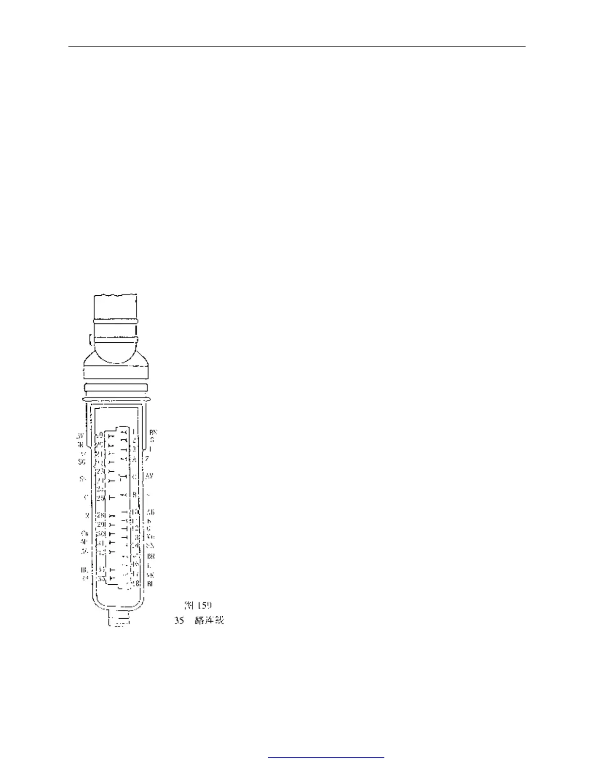
35-way connection line
PDF 文件使用 "pdfFactory Pro" 试用版本创建 www.fineprint.com.cn