Maintenance Manual for Chery·Windcloud Marelli EFI System
Chapter One: Operating Principle for
Marelli EFI Control and Execute
Components
1. Intake Pressure and Intake Air
Temperature Sensor
Purpose: to detect absolute pressure of
intake manifold from 10-115KPa and intake
air temperature, to provide engine load
information, and to identify the height above
sea level and to conduct intake pressure
compensation according to the intake
pressure at certain engine speed and idle
speed.
Composition and principle: this sensor has
two functions (i.e. manifold absolute
pressure sensor and intake temperature
sensor integrated in one unit), and is
installed above pressure-stable cavity to
detect absolute pressure of intake manifold
(pressure-stable cavity), which is used to
control fuel injection and ignition.
Pressure-sensitive element inside intake
pressure sensor detects signal of intake
manifold pressure for injection pulse width
control of EFI system. This sensor also
serves as the substitute of a sensor of engine
load signal.
Intake air temperature sensing element is
an NTC (Negative Temperature Coefficient)
resistor, which is similar to that of water
temperature sensor. While the intake air
temperature increases, the resistance value
decreases. And engine ECU monitors the
variation of intake air temperature via a
comparison circuit inside.
Failure diagnosis: The monitor circuit
inside ECU detects sensor circuit troubles
such as open circuit, short circuit and sensor
damages, etc. In case ECU detects any
sensor output signal that goes beyond output
characteristic curve, the sensor is diagnosed
as failed by ECU.
For example: when intake pressure is
higher than upper limit or lower than lower
limit, ECU detects sensor failure (in case
that intake pressure is lower than lower limit
when starting, ECU is able to recognize the
starting condition), and the engine fault
indicating lamp goes on. Under this
condition the engine works in failure mode.
When intake temperature sensor signal
exceeds either upper or lower limit, engine
ECU will light fault indicating lamp to
remide driver that engine assumes failure
mode.
Installation: to be installed on pressurizer.
Troubleshooting: mainly check if there is
short circuit or open circuit on the
connection between 4 lines on senosr and
ECU.
If there is short circuit, open circuit or
grounding between sensor wire harnesses.
Check system for air leakage, and check if
all connections are in good condition.
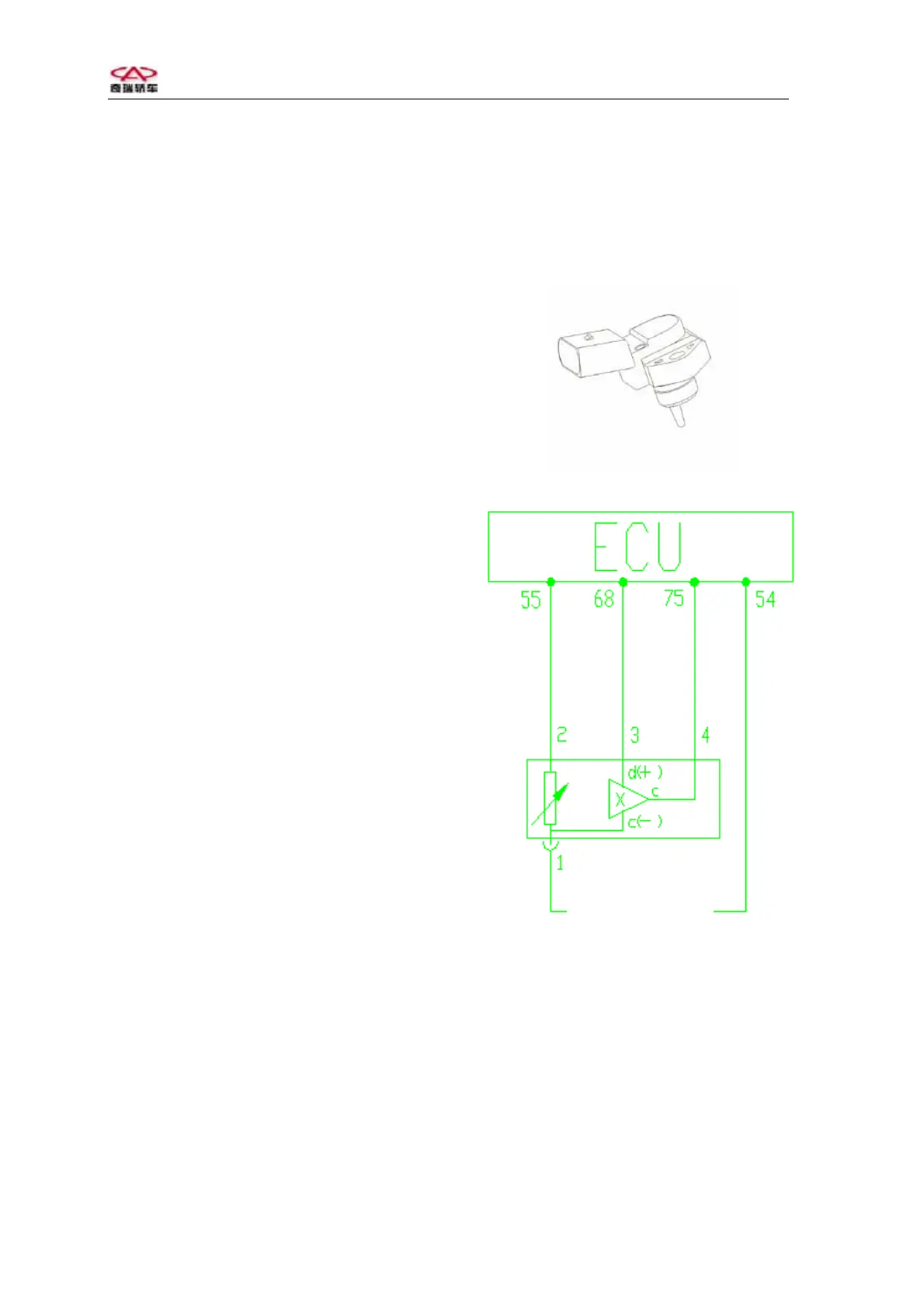
Manifold absolute pressure /intake air temperature sensor
Intake temperature
pressure sensor
Circuit diagram of manifold absolute pressure and intake
air temperature sensor
Pins: 1# is grounded (connecting ECU 54#);
2# outputs temperature signal
(connecting ECU 55#);
3# connects with standard 5V power
source (connecting ECU 68#);
4# outputs pressure signal (connecting
ECU 75#).
1