Maintenance Manual for Chery·Windcloud Marelli EFI System
2. Throttle Position Sensor
Purpose: this sensor is designed to provide
ECU with information of throttle angle. As
per such information, ECU obtains
information of engine load and operating
condition (for instance: start-up, idle speed,
reverse, partial load and full load) as well as
of acceleration and deceleration. This sensor
has three wires, and the throttle opening can
be detected by ECU via monitoring voltage
variation.
Composition and principle: Consisting of
two compass sliding contact resistors and
two sliding contact arms, throttle position
sensor is an angle sensor that outputs linear
signals. The axes of contact arms are on the
same axial line with throttle axis, with 5V
power supply voltage U
S being applied to
both ends of each contact resistor. When
throttle turns, contact arms turn along with it
and move on sliding contact resisters,
educing potential of contacts U
P as output
voltage. This sensor is actually an angle
potentiometer. ECU adopts Up/Us votage
ratio to avoid change in output signal due to
fluctuation in engine voltage.
Failure diagnosis: ECU monitors throttle
angle, and detects sensor failure when
output signal exceeds upper or lower limit.
In addition, ECU detects sensor circuit
errors such as short circuit and open circuit.
In case any of these errors is detected,
engine will work in failure mode, and fault
indicating lamp will go on.
Signal output: this sensor outputs
0.5V-4.9V DC voltage signals. Rotate the
sensor to test the output signal, which shall
be a continous signal without fluctuation or
interruption.
Installation: allowable tightening torque
for fastening screw is 1.5Nm-2.5Nm.
Troubleshooting: mainly check if there is
short circuit or open circuit on the
connection between 3 lines on senosr and
ECU.
Check to see if there is short circuit, open
circuit or grounding between sensor wire
harnesses.
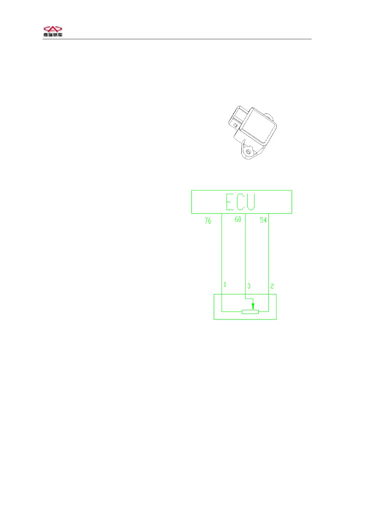
Throttle position sensor
Throttle position senso
Circuit diagram of throttle position sensor
Pins:
1 throttle position sensor (ECU 76#)
2 sensor signal ground (ECU 54#)
3 sensor signal (ECU 60#)
Warning: under most circumstances, the
removal of throttle position sensor is not
allowed.
2