(1) Throttle valve body
Throttle valve body calculate air intake volume upon throttle pedal depressing status. Auxiliary
air intake volume is regulated by step motor when engine idles.
To avoid condensation and freezing under some conditions, throttle valve regulator bar
is against anti-stuck screw preventing throttle from full closed. . The anti-stuck screw is
adjusted during throttle valve body calibrating by manufacturer and do not turn the screw.
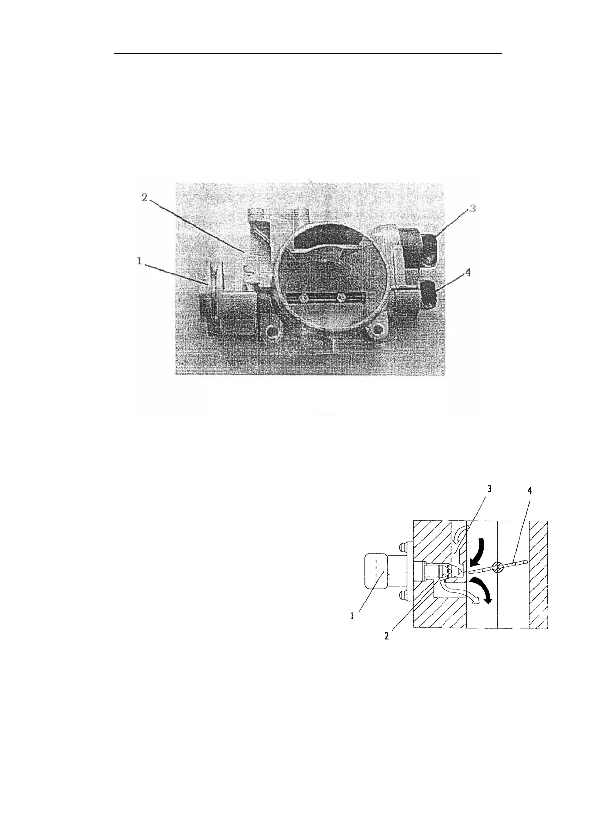
Fig 5 Outside Drawing of Throttle valve
1. throttle cable coil 2. Anti-stuck Screw 3.step motor 4.throttle position sensor
(2) Idle step motor
Idle step motor is used for controlling
idle speed ,directly fixed on throttle valve
body consists of one step motor and
screw/worm retard unit which change the
rotational movement of locking pin to linear
movement. After receiving control
command of ECU, step motor axially
moves valve spindle (about 0.04mm/step)
using screw/worm unit , by which change
by-pass air charge volume when engine
idles to control idle speed.
When temperature is at 20℃, coil
resistance is R=53±10Ω. The maximum
air charge is achieved through backing 200
steps of locking valve. The amounts of
working step is determined upon engine operating conditions including warming up, A/C on
etc.
Fig 6 Idle Control Valve Operation Theory
1.Step motor 2. control valve 3.by-pass hole
4.throttle valve