3. Control system
(1) ECU
ECU is located in the cabin of engine, connected to wiring harness via 80-pin interface.
ECU is used for handling signals from various sensors and controlling actuators to obtain
optimum operating conditions..
Comparing to the previous mode, it has added many functions. But due to using of
many customized circuits of special functions, it has powerful integration, compact structure,
and small size.
ECU handle following signals:
- battery voltage;
-intake manifold absolute pressure ;
-Top Dead Center;
-throttle position;
-air intake temperature;
-Engine coolant temperature;
-A/C operation;
-oxygen sensor signal;
-knocking sensor signal。
Air charge efficiency is calculated upon managed intake manifold absolute pressure,
intake air temperature, engine speed and throttle position, by which air charge volume in
cylinder is obtained.
ECU controlsas below:
- Control fuel injection by controlling open time of fuel injector;
-Idle step motor;
-Four high voltage output ignition coil;
-carbon canister solenoid;
-A/C compressor;
- Warning indicator
Besides those functions, ECU can also controls:
-all self-diagnostics strategies on input sensors
and output actuators;
-“Wrong” signal recovery strategy on basic valid input signal;
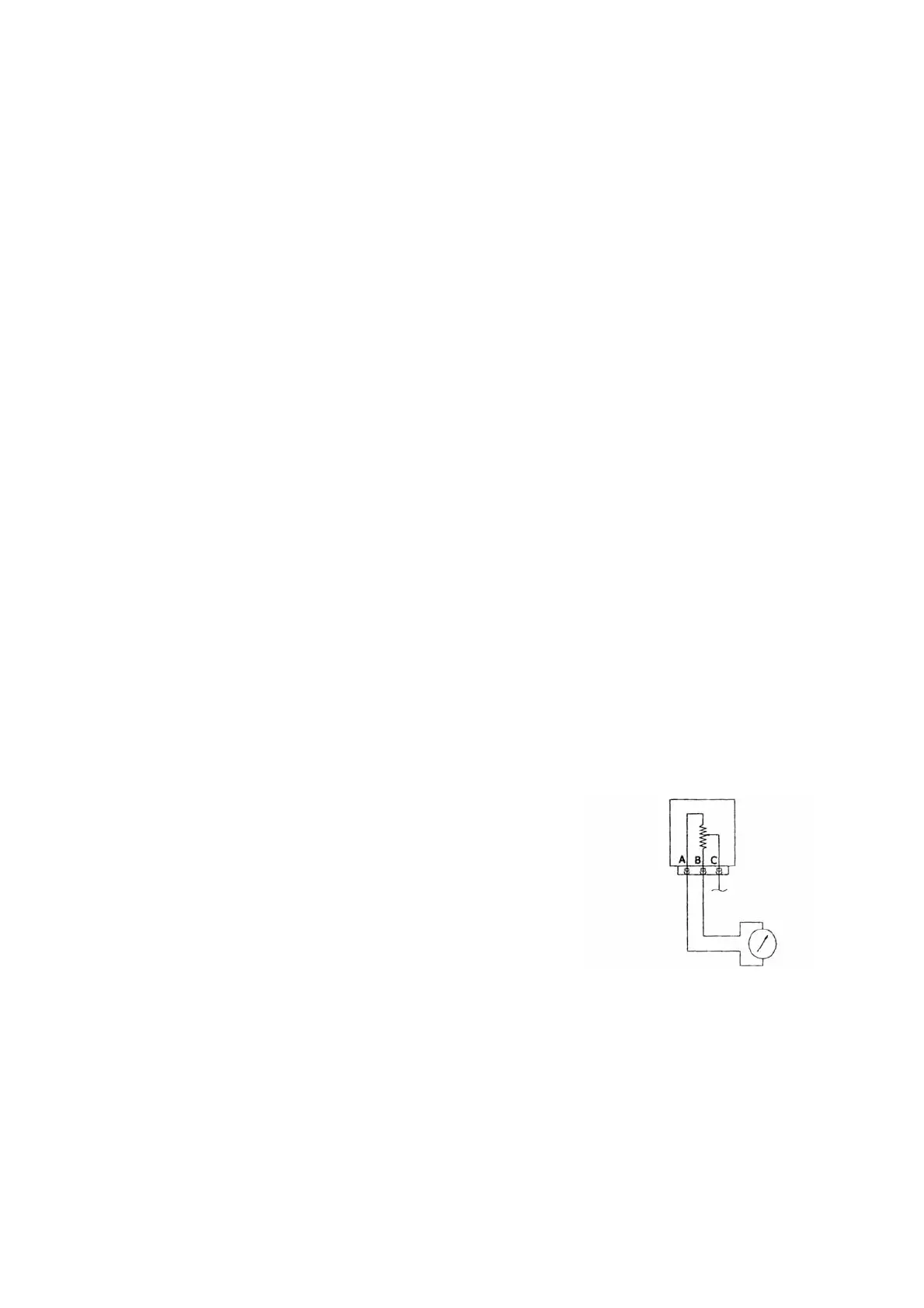
Fig 7. Throttle valve positio
sensor
A. Voltage positive B. ground C.
-Engine anti-theft function
(2) Throttle position sensor
Throttle position sensor is used for measuring throttle opening, determining idle, full