HIPOT Tester 19071/19072/19073 User’s Manual
2-4
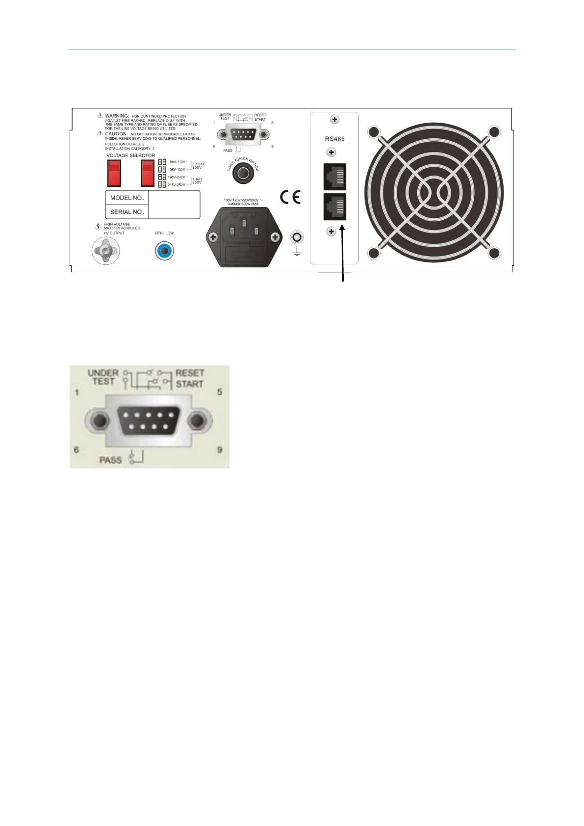
The rear panel of link test model of 19073 + RS485 is shown as below:
(11)
(1) REMOTE CONTROL
■ The connection diagram of remote control signals is as the following.
■ START: The input terminal for start test signal.
■ RESET: The input terminal for stop test signal.
■ COM: The common input terminal for START and RESET signal.
■ UNDER TEST: This terminal will short-circuit when in test mode, thus it can be used to
control the external signal. The connecting point specification is 115V AC, current less
than 0.3A. The action time is from the instrument enters the test mode until it is reset or
completes the test.
■ PASS: This terminal will short-circuit when the DUT passes the tests, thus it can be used
to control the external signal. The connecting point specification is 115V AC, current less
than 0.3A. The action time is from the DUT is passed until it is reset.
(2) VOLTAGE SELECTOR: Input Power Range Switch
■ To change the input AC power source for the following 4 types:
Voltage range 90V ~ 110V AC (3.15AT, 250V)
Voltage range 108V ~ 132V AC (3.15AT, 250V)
Voltage range 198V ~ 242V AC (1.6AT, 250V)
Voltage range 216V ~ 250V AC (1.6AT, 250V)