HIPOT Tester 19071/19072/19073 User’s Manual
2-20
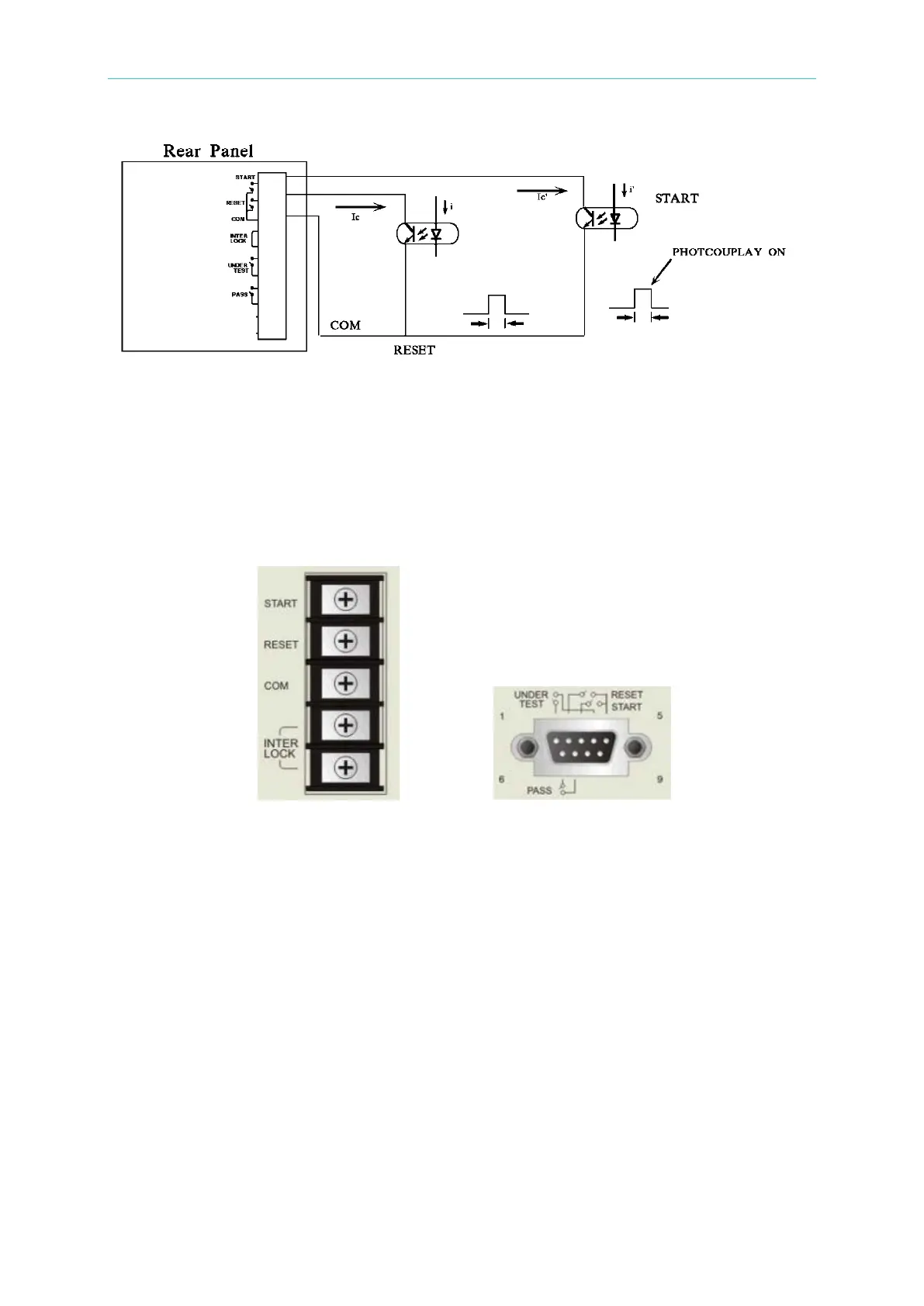
Figure 2-3
■ Either the relay switch control in Figure 2-1 or the coupler control in Figure 2-3 uses the
contact of components for control action. It can prevent the error operation from
interference effectively. Though the system has a lot of precautions, you would still need
to watch out the interference caused by the measurement system settings.
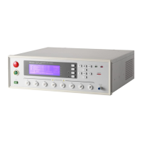
■ Pin diagram of REMOTE CONTROL as Figure 2-4. When users to control by external,
please remember this pin diagram.
REMOTE I/O 9 Pin D-Sub
Figure 2-4
2.5.5 Output Signal
This instrument has indicator and beeper for indication signals. The output signals in the
system rear panel are:
■ UNDER TEST: This terminal will short-circuit when in test mode, thus it can be used to
control the external signal. The connecting point specification is 115V AC, current less
than 0.3A.
■ PASS: This terminal will short-circuit when the DUT passes the tests, thus it can be used
to control the external signal. The connecting point specification is 115V AC, current
less than 0.3A. The action time is from the DUT is passed until it is stopped.
more