Panel Description
(6) Slot for interface:
There are 5 signal controlled interface cards as following:
a. Scan Interface card
b. Handler Interface Card:
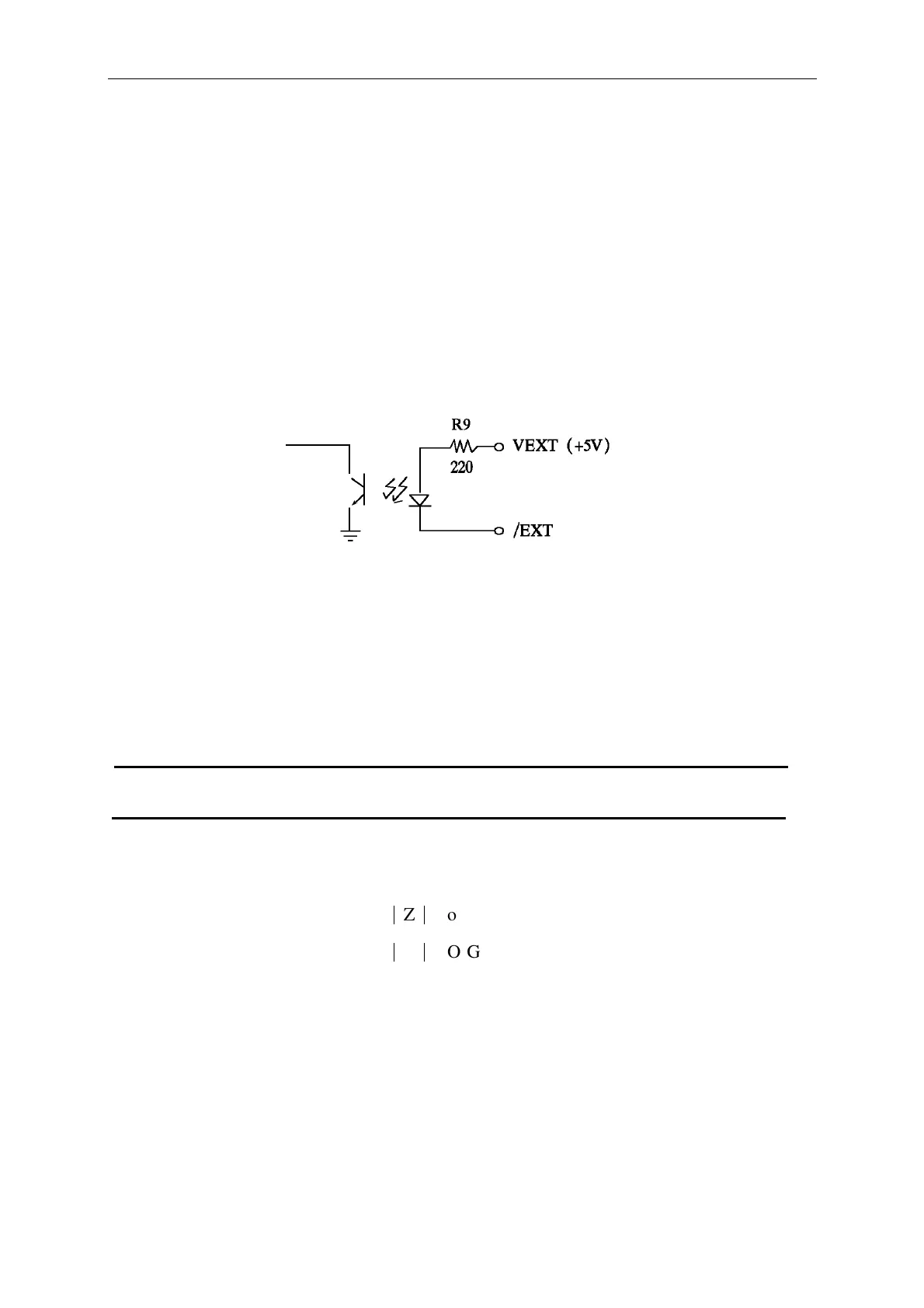
Handler interface control signal as table 4-1 shown, when signal action, from open remit
driver signal transmit to make Handle signal is Low, when not action is High.
External lead signal max to 30V, positive voltage to start, and has enough rising resistance to
limit the action signal (LOW), VEXT = +5V the max current 16mA.
If VEXT is greater +15V, the R9 would be replace by other proper resistor to meet the
specification.
When input signal action, it has to additional VEXT, Low signal voltage must less than 0.4V,
can not be a negative value. High signal voltage must grate than 2.5V, can not higher than
MAX 5V, output current 1mA.
c. Printer Interface Card
d. RS-232 Interface Card (with CPK software use for test data statistic analysis purpose)
Table 4-1Handler interface signal control form
Signal Name Pin No Function
VEXT 1 Add in polarity voltage, loading current is limited in 16mA.
/EOT 3 "Test ending", judge signal effective.
/PASS 4 L/C/R/
|
Z
|
Good.
/FAIL 5 L/C/R/
|
Z
|
NO-Good.
/ACQ 6 "Data collection finished", DUT can be moved.
/EXT 7 external trigger.
GND 8, 15 Ground
e. DCA Control Interface