Panel Description
4.4.9 Pins Parallel Test Description
Want to test the transformer Pin and Phasing setting must be under the test condition screen of
the PIN AND PHASING SETTING, the setting is to move the cursor to the pins which need
to be tested the multi-parallel test.
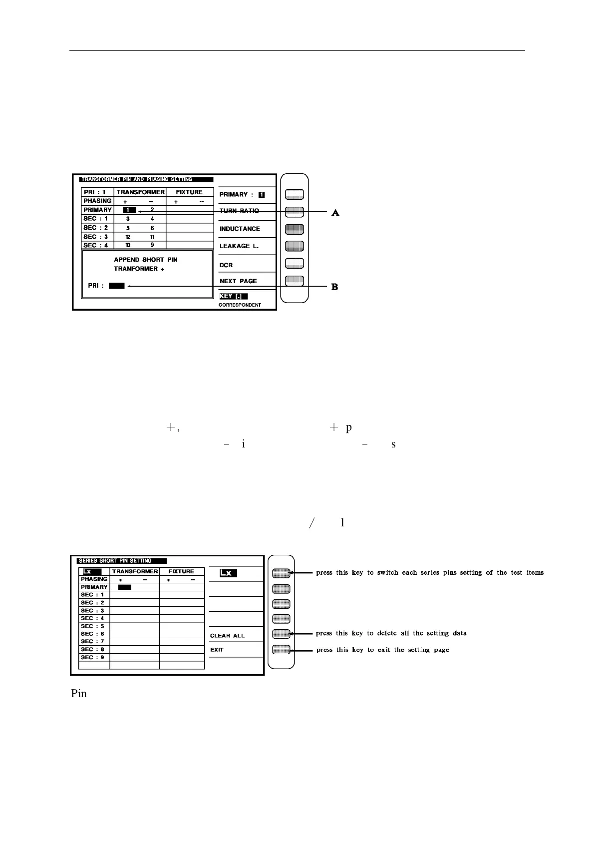
Above figure description
APPEND SHORT PIN (TRANSFORMER +) the meaning is the input pin position is parallel
test set up and transformer is positive phase (TRANSFORMER +,cursor A show pin position),
short parallel, parallel pins max. can enter to 5 PIN, enter method is at cursor B known pin
position input the intend to parallel test than press [Enter] key, for exit set up scre en only
press down [Reset] key, and back to transformer pin set up screen, because cursor A position
TRANSFORMER
+
, so the display and transformer
+
phase short parallel set up, if cursor
A position at TRANSFORMER
﹣
, it display for transformer
﹣
phase short parallel set up.
4.4.10 Pins Series Test Description
Want to test this function must be under the setting screen of the PIN AND PHASING
SETTING, the setting is that press the key [Meas
∕
Display] then shows the pins setting as
below:
Pin series testing can according to test items and set up the series position, set up method is
selected the test item, than according to the series pin need to be set to the winding, for exit
the display, only press exit key. If has use pins auto correspond function, only set up
transformer pins.