Handler Interface (Option)
7. Handler Interface (Option)
7.1 General
If you have the HANDLER INTERFACE option, connect from the HANDLER INTERFACE
on the rear panel to a handler. Connect the control lines to the handler. See Table 7-1. As
indicated in the specifications at the front of this manual. The output signal come from
open-collector drivers that pull each signal line to a low voltage when that signal is active and
let it float when inactive. Each external circuit must be powered by a positive voltage, up to
30V(max), with sufficient impedance (pull-up resistors) to limit the active-signal (logic-low)
current to 16mA(max).
Caution :
Each relay or other inductive load requires a CLAMPING DIODE (rectifier) across it
(cathode connected to the power-supply end of the load) typically.
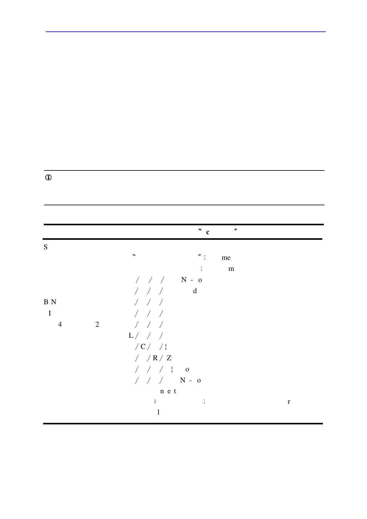
Table 7-1 Handler Interface Key
Signal Name Pin No. Function (All signal
〝
active low
〞
)
START 25 Initiates measurement (External Trigger).
EOM 8
〝
End of measurement
〞;
judgment signals are valid.
ACQ over 27 "Data acquisition over"
;
DUT removal OK
BIN 0 19 Q
∕
D
∕
R
∕
¦Z¦ No-Good
BIN 1 2 L
∕
C
∕
R
∕
¦Z¦ Good
BIN 2 20 L
∕
C
∕
R
∕
¦Z¦ Good
BIN 3 3 L
∕
C
∕
R
∕
¦Z¦ Good
BIN 4 21 L
∕
C
∕
R
∕
¦Z¦ Good
BIN 5 4 L
∕
C
∕
R
∕
¦Z¦ Good
BIN 6 22 L
∕
C
∕
R
∕
¦Z¦ Good
BIN 7 5 L
∕
C
∕
R
∕
¦Z¦ Good
BIN 8 23 L
∕
C
∕
R
∕
¦Z¦ Good
BIN 9 6 L
∕
C
∕
R
∕
¦Z¦ No-Good
1,7 Ground connection
9 DC bus(
﹢
5V) available
;
commonly for opto-couplers.
Limit the load to 25mA(max.).
The input signal is also active low and also requires a positive-voltage external circuit,
which must pull the signal line down below 0.4V, but not less than 0V, i.e., not negative.
The logic-low current is 0.4mA (max.). For the inactive state (logic high) the external
circuit must pull the signal line above +2.5V, but no above +5V.