Parallel Operation
4-1
4. Parallel Operation
4.1 Multiple Communication Parallel Connection
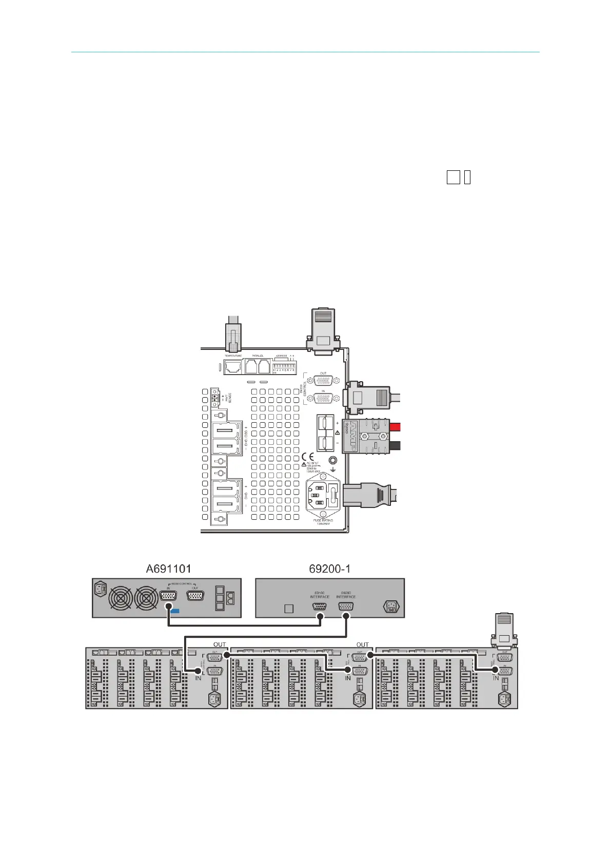
Single connection is connecting D-Sub communication line on Chroma 69200-x controller via
its rear panel to 69225/69212 series rear panel and connects termination resistor as Figure
4-1 shown.
Multiple parallel connection are taking 3 sets parallels of machine A, B and C as example, the
wire connections are shown as Figure 4-1 and Figure 4-2. The connection hole of the last
D-Sub OUT in parallel structure should be connected to termination accessories to ensure
communication normal. Similarly, obey this connection for parallelling more machines.
Figure 4-1
Figure 4-2
Each instrument has 4 channels and ADDRESS DIP switch at rear panel is the basis for
distinguishing channel as Figure 4-3 shown.
A. DIP switch pin1~pin6 are channel number setting pins which use binary method for
 Loading...