Regenerative Charge/Discharge Tester 69225/69212 Series User’s Manual
4-2
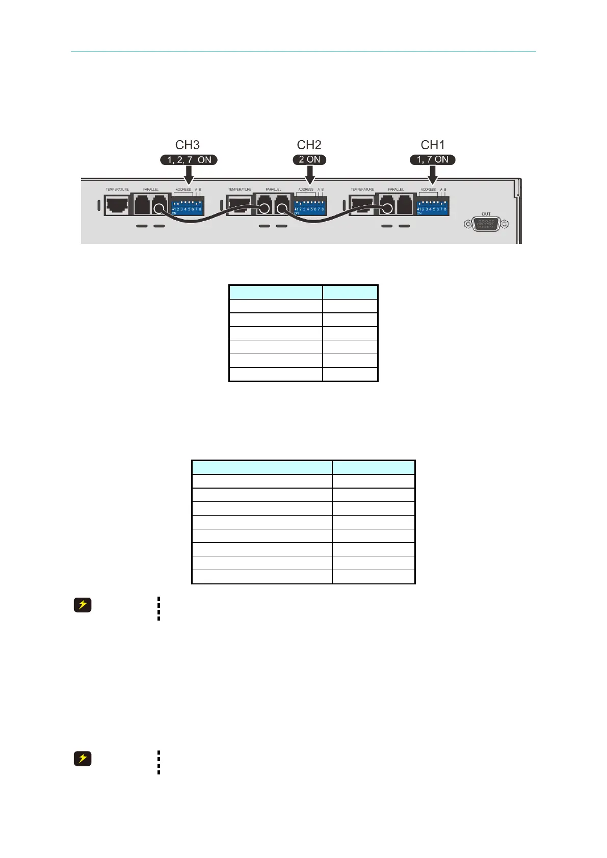
setting channel number. The switch corresponding positions are shown as Table 4-1.
B. DIP switch pin7 is termination resistor setting pin of Current Sharing CAN BUS. If output
is in parallel, the 1
st
channel and the last one need to be set.
Figure 4-3
Table 4-1
Each instrument default channel numbers are 1~4. When the system operation are paralleling
multiple 69225/69212 series, we recommend to follow number settings in Table 4-2 to avoid
channel number repetition that causing system misjudged.
Table 4-2
When users use multiple channel, remember to revise default ADDRESS
number (DIP switch 1~6) and set termination resistor (DIP switch pin7).
4.2 Connecting Output Parallel Current Sharing
When the instrument need to be applied on output parallel mode, transmit parallel information
via Parallel wire and set the termination resistor of 1
st
channel and the last one [DIP switch
pin7]. When the power is on, the instrument auto detects parallel number via Parallel
transmission line and use channel with lowest coding as Master and other channels as Slave.
When users use parallel mode, it is necessary to connect Parallel wiring
correctly, otherwise it may cause system connection error.
 Loading...