Chromalox 3101 Operator's Manual 7
1
2
3
4
5
6
7
8
9
10
11
12
13
14
15
16
17
18
19
20
21
22
23
24
25
26
27
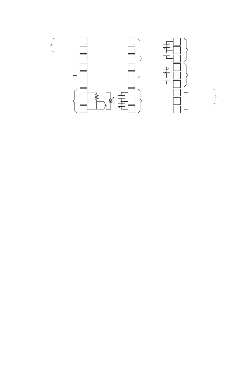
Figure 2.4 Wiring Terminal Identifi cation
Sensor Input Wiring
Sensor Input Wiring Notes:
•
Sensor leads (thermocouple and RTD) should not be
run together in the same conduit as power wiring.
• Twisted pair, shielded wire is recommended for
sensor connections.
• False process readings can occur if the sensor
wire is exposed to electrical noise.
• Ungrounded thermocouples are recommended.
• If thermocouple extension wire is required, it must
be the same type as the thermocouple (i.e. if a
Type K thermocouple is used, then Type K exten-
sion wire must be used).
• Thermocouple wires should connect directly to
the controller terminals. Do not use copper crimp
terminals or solder terminals to make connections.
• If shielded thermocouple wire is used, the shield
must be grounded at one end only, preferably at
the shield ground terminal on the controller, as
shown in Figure 2.5.
• Three wire RTDs are recommended for greatest
accuracy.
• Standard shielded copper wire is recommended
for RTD extensions.
+24 Vdc Output
Analog Output
Not Used
Common
Sensor Input
RTD TC
Common
Digital
Input
4-20mA
Digital
Comm.
Not Used
Alarm #2
Output
AC Common
100/240 Vac or
Shield Ground
Instrument
Power
Limit Control Output
Alarm #1 Output

 Loading...

