Chromalox 3101 Operator's Manual 3
Section 2
Installation
On receipt of your 3101 controller, immediately
make note of any visible damage to the ship-
ment packaging and record this damage on the
shipping documents. Unpack the controller and
carefully inspect it for obvious damage due to
shipment. If any damage has occurred, YOU must
fi le a claim with the transporter, as they will not
accept a claim from the shipper.
If the controller will not be immediately installed
and placed into operation, it should be stored in
a cool, dry environment in its original protective
packaging until time for installation and operation.
Temperature extremes and excessive moisture
can damage the instrument.
Inspection
and
Unpacking
Switch
Settings
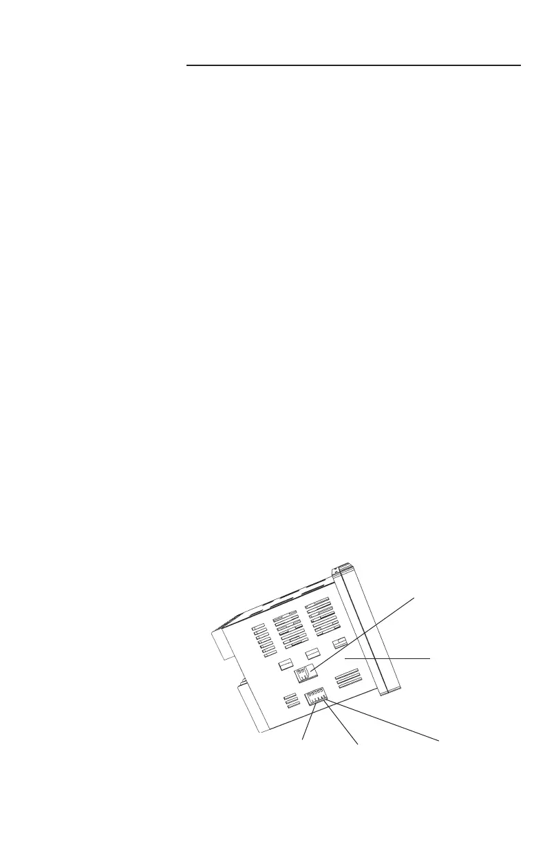
The 3101 has up to seven (7) hardware switches
located on the bottom of the controller. The
switches are accessible through cutouts in the
controller housing and do not require that you
remove the controller from its housing to access
the switches.
Figure 2.1 identifi es the switches. Instructions for
switch settings are given in the corresponding
sections of the manual.
Figure 2.1
Sensor Selection
Dip Switch
Settings
Controller Bot-
tom Surface
Switches #1 and #2
Digital Communications
RS422/RS485
Switches #1, #2 and #3
Sensor Input
Switch #4
(not used)
Switch #5
Analog Output
Signal

 Loading...

