48 Chromalox 3101 Operator's Manual
Figure 9.5
RS422A
Connector
Pin
Designations
(Typical)
DB - 9
4
5
8
9
3
XMT +
XMT -
RCV +
RCV -
GND
DB - 25
14
2
16
3
7
XMT +
XMT -
RCV +
RCV -
GND
RS485 Communications
RS485 defi nes a tri-state interface with no
accompanying physical connector. Reference
manufacturer’s specifi cations for computer
interconnections.
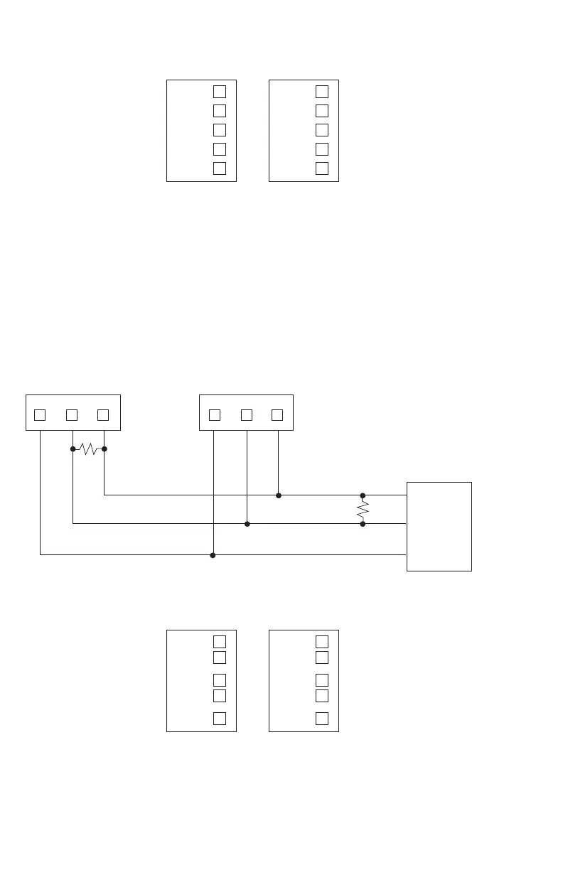
Figure 9.6
RS485 Wiring Connections (2-wire)
3101 3101
GND
23
R/T-
22
R/T+
21
GND
23
R/T-
22
R/T+
21
R/T+
R/T-
GND
Note: 270 resistors recommended across receive line on computer and last controller.
270
270
Figure 9.7
RS485
Connector
Pin
Designations
(Typical)
DB - 9
4
8
5
9
3GND
R/T -
R/T +
DB - 25
14
16
2
3
7GND
R/T -
R/T +
Computer with RS485 Inter-
face Card

 Loading...

