8 Chromalox 3101 Operator's Manual
Thermocouple Inputs
It is important to observe polarity (+, -) when con-
necting thermocouple leadwires. The table below
shows ANSI color coding for the thermocouples
used with this instrument.
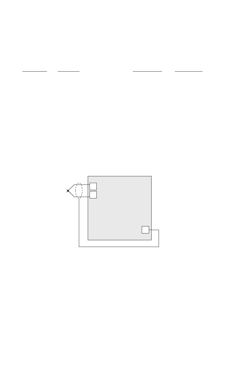
Make the thermocouple wiring connections to
terminals as shown in Figure 2.5.
T/C Type Material Polarity (+) Polarity (-)
B Plat, 30% Rhodium/ Gray Red
Plat, 6% Rhodium
J Iron/Constantan White Red
K Chromel/Alumel Yellow Red
E Chromel/Constantan Purple Red
T Copper/Constantan Blue Red
R Plat, 13% Rhodium/Plat Black Red
S Plat, 10% Rhodium/Plat Black Red
Figure 2.5
Thermocouple
Connections
3-Wire RTD Inputs
When making the 3-wire RTD input connection, it
is important to make the resistance of all three ex-
tension leadwires equal by using the same gauge
and same length of wire for optimum leadwire
compensation. Chromalox recommends 3-wire
RTDs for greatest accuracy, and standard shield-
ed copper wire for RTD extensions. Make 3-wire
RTD connections to terminals 7, 8 and 9 as shown
in Figure 2.6 on the following page.
8
9
+
-
Shield Gnd
18
3101

 Loading...

