34
9. Inductive and Transformer Coupled Load Guidelines
10. Communications Port (Modbus RTU/RS485)
The model C4 should not be used for Inductive or Transformer Coupled Loads. The model C4-IR is capable of be-
ing used for these types of loads. Please refer to the C4-IR Hardware Manual for more details.
A network typically has a Master that “manages” com-
munication by means of “commands,” and Slaves that
carry out these commands.
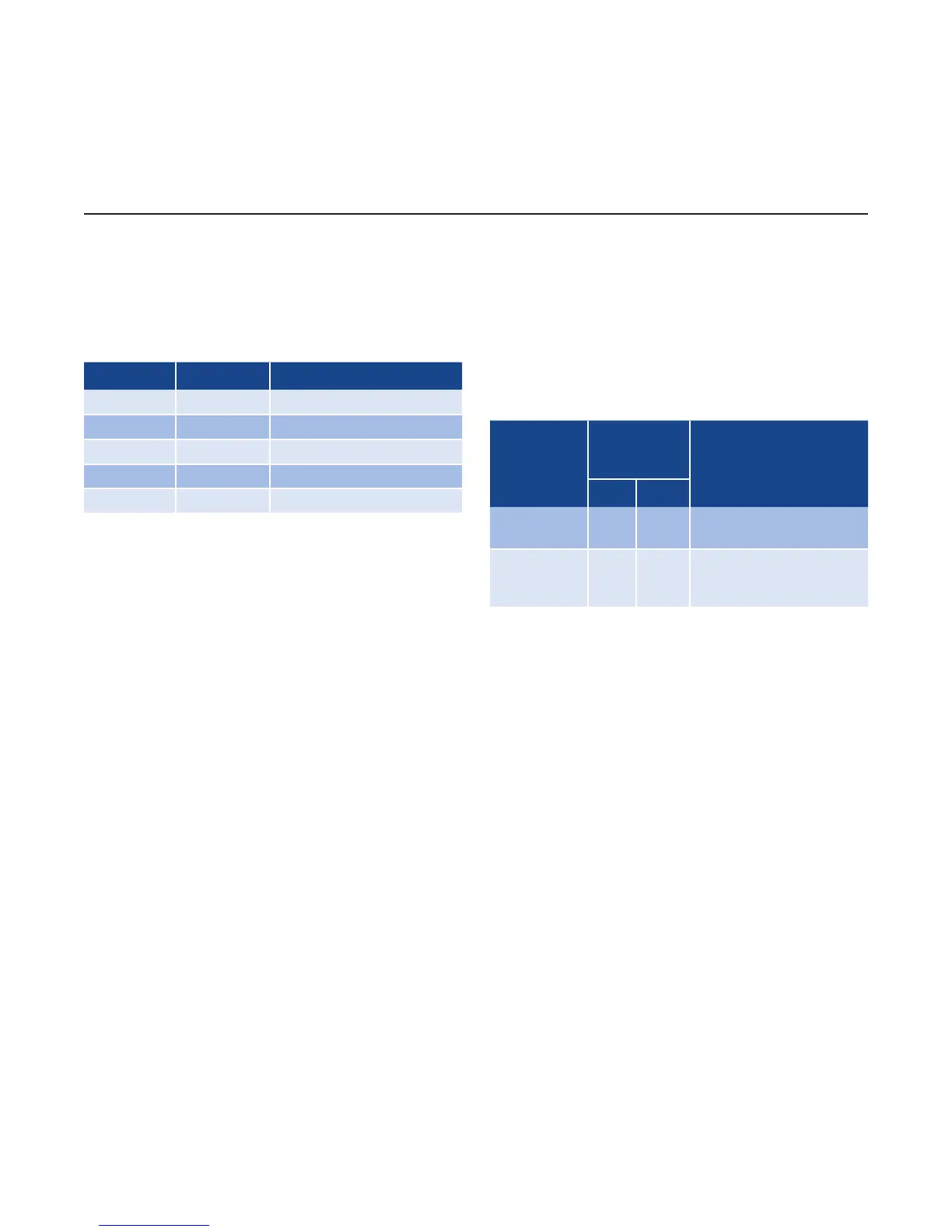
Parameter Default Range
ID 1 1...99
BaudRate 19.2kbits/s 1,2...57.6k bits/s
Parity None Parity/Odd Parity/None
StopBits 1 -
DataBits 8 -
C4 modules are considered Slaves to the network mas-
ter, which is usually a supervision terminal or a PLC.
They are positively identified by means of a node ad-
dress (ID) set on rotary switches (tens + units).
A maximum of 99 C4 modules can be installed in a se-
rial network, with node address selectable from “01”
to “99” in standard mode in which each C4 identifies
4 zones with sequential node address starting with the
code set on the rotary switches.
C4 modules have a ModBus serial (Serial 1) and, op-
tionally (see order code) a Fieldbus serial (Serial 2) with
one of the following protocols: Modbus RTU, Profibus
DP, CAN open, DeviceNet, and Ethernet Modbus TCP.
The ModBus RTU port 1 has the following factory set-
tings (default):
Procedures
Position of
Rotary
Switches
DescriptionTens Units
AutoBaud 0 0
It enables to set the
correct BaudRate Value
AutoNode* A 0
It enables to transfer
the correct node (ID)
address (tens)
The following procedures are indispensable for the
Modbus protocol. For the other protocols, see the spe-
cific manuals. The use of rotary switches (A...F) letters
is for particular procedures described in the following
paragraphs.