10
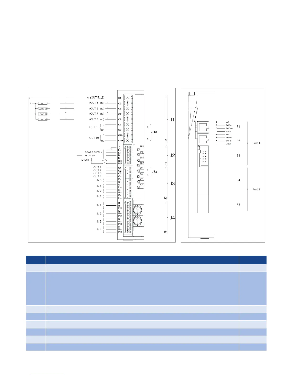
7.3 Input & Output Connections
• Use adequately compensated cable for thermocou-
ple inputs. Maintain polarity by avoiding junctions
on the cables.
• If using a grounded thermocouple, the connection
must be at a single point.
• For RTD inputs, use copper extension cables and
avoid junctions on the cables. Resistance must not
exceed 20 Ohm.
• For 2-wire RTDs, make the connection indicated in-
stead of the third wire.
• Refer to the applicable Connectors Detail starting in
section 7.6
7.4 LED Logic
LED Description Color
RN RUN - Flashes during regular operation Green
ER
ERROR (Fault Condition) - Illuminates when a fault is present
Lo = Process Variable value < Lo.S
HI = Process Variable value > Hi.S
Sbr = Sensor interrupted or input values over maximum limits
Err = RTD third wire interrupted for Pt100 or input values below minimum
ER = (red) flashing: Alarm temperature OVER_HEAT (STATUS.STRUMENTO 4 bit 1)
Red
DI1 State of digital input 1: DI1 Yellow
DI2 State of digital input 2: DI2 Yellow
O1 State of output 1: O1 Yellow
O2 State of output 2: O2 Yellow
O3 State of output 3: O3 Yellow
O4 State of output 4: O4 Yellow
TRIAC Logic/Analog Relay