18
7.8 Serial Communication Ports
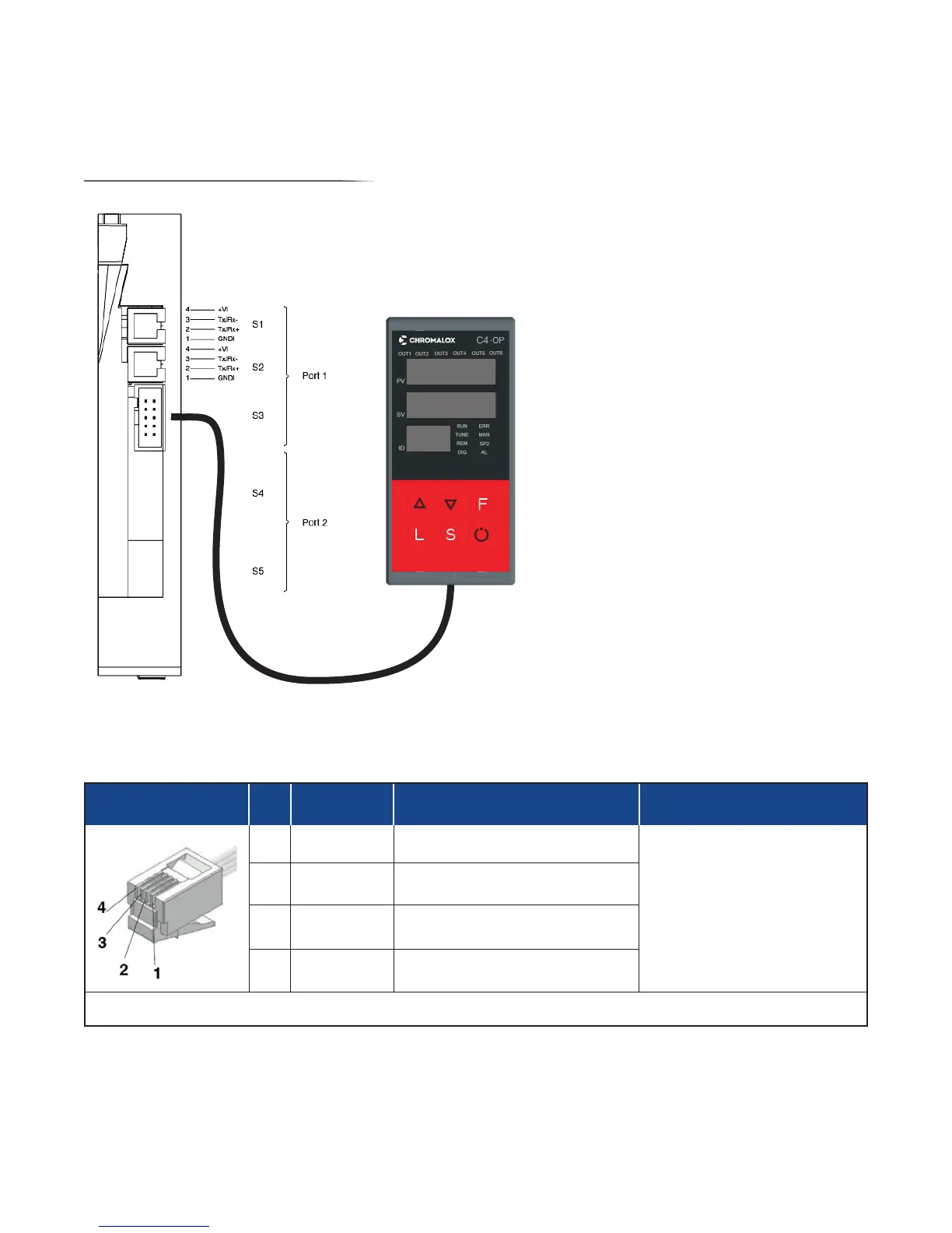
7.8.1 Port1 (Standard Local Bus): Connectors S1, S2, S3
Modbus RTU/RS485 Serial Interface
Connector S3 accepts the C4-OP local
interface terminal. See th
for more detail.
1 9
2
F
1
9
0
F
0 1
Connector S1/S2
RJ10 4-4 Pin Pin Name Description Note
1 GND1 (**) -
(*) Enable #8 DIP Switch on
last device on Modbus RS485
line
(**) Connect the GND signal to
Modbus devices with a line
distance > 300 ft. (100 m)
2 Tx/Rx+ Data reception/transmission (A+)
3 Tx/Rx- Data reception/transmission (B-)
4 +V Reserved -
Cable Type: Flat telephone cable for pin 4-4 conductor 28 AWG