8
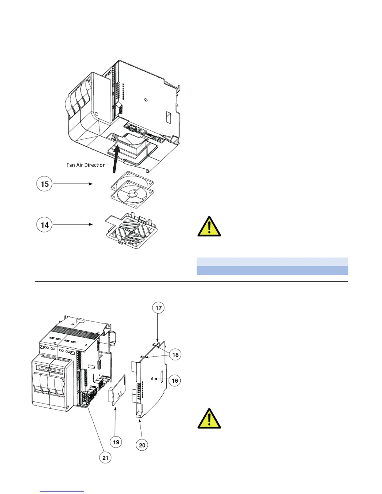
6.2 Cooling Fan
6.3 Inserting a New Field Bus Interface Card
PERIODIC CLEANING
Every 6-12 months (depending on the dust level of
the installation) blow a compressed air jet downward
through the upper rectangular cooling grilles (on the
side opposite the fan). This will clean the internal heat
dissipater and the cooling fan.
IN CASE OF OVERHEAT ALARM
If periodic cleaning does not eliminate the problem, do
as follows:
a. Remove the fan support grille by detaching the two
support tabs
b. Disconnect the fan connector from the board
c. Check the condition of the fan
d. Clean or replace the fan
NOTE: Ensure that the air flow arrow on the fan is
pointing towards the heat sink e Insert the connec-
tor into the board
f. Insert the fan support grille until it attaches
g. Power up the device and check fan rotation when at
least one load is on
Before and during the inspection/
maintenance, cut power to the fan
controller and verify that the system
is isolated for operator safety.
14 Support Grill
15 Fan
To insert a communication module, the Field Bus
Interface Board compartment must be accessed.
Follow these steps:
1. Remove the Fieldbus compartment cover screw
(16)
2. With a flat screwdriver, gently apply pressure at (18)
3. Remove compartment cover (17)
4. Insert Fieldbus card (19) into the proper connector
(21)
5. Remove applicable communication port tab (20) on
cover (17)
6. Carefully replace compartment cover (17)
7. Tighten compartment cover screw (16)
Before attempting board replacement,
ensure that power to the controller
has been cut and verify that the
system is isolated for operator safety.

 Loading...


