7
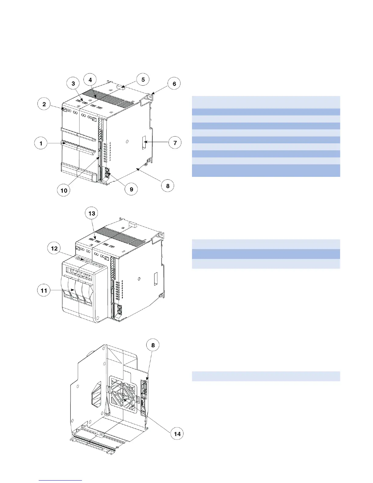
6. Controller Overview
6.1 Layout
1.
Front DIN rail mount for the C4-OP programming module.
This mount is only present on models without fuse holders.
2. Screwdriver access to power connection screws.
3. Power supply connection terminals
4. Heat sink ventilation screen: DO NOT OBSTRUCT
5. Spring clamp release for rear DIN rail.
6. Fastening slots for additional mounting security.
7. DIP switches for controller function / load configuration.
8. Communication ports (Port1, Port2).
9. Rotary switches for setting node address or number
10.
Input signal & low voltage power supply terminals
(J1, J2, J3, J4)
11. Fuse holders. (Only available on 30KW and 60KW models).
12. Terminals for fuse holder connection (F1, F2, F3, F4/N)
13. Terminals for load power connection (U1, U2, U3, U4)
14. Air intake / fan protection screen: DO NOT OBSTRUCT