11
7.5 Rotary Switches
7.6 Connector Detail
Switch Drescription
0
8
D
5
E
6
F
7
3
B
1
9
2
A
4
C
X1
X1
0
8
D
5
E
6
F
7
3
B
1
9
2
A
4
C
Defines Address of Controller Module
Available address: 00...99
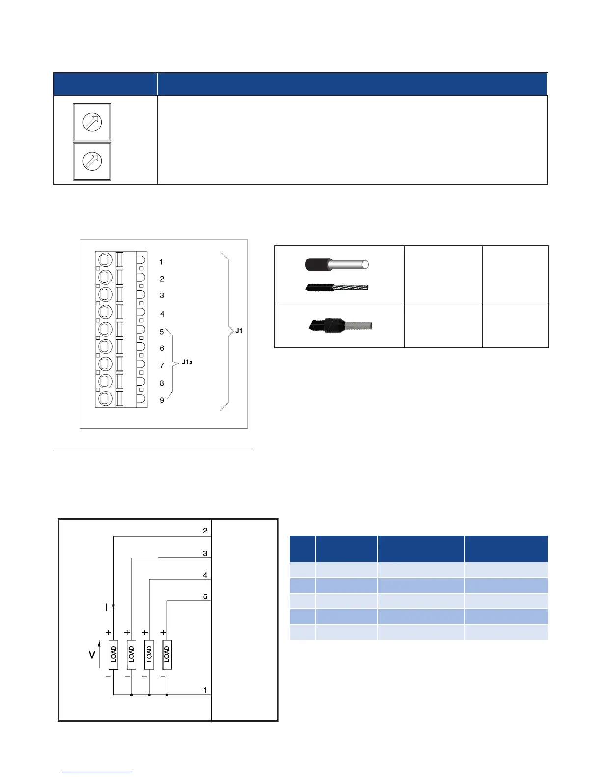
7.6.1 Connector J1 / J1a (Note: If Auxiliary Outputs O5 - O8, are present, connector J1a becomes J1.)
Outputs 5 - 8: Logic or Analog Output Type
Logic outputs: 18 - 36Vdc, max 20mA
Analog outputs: Voltage (default): 0 - 10V, 2 - 10V, max 25mA or Current: 0 - 20mA, 4 - 20mA, max 500Ω
0.2 - 2.5mm
2
24-14 AWG
0.25 - 2.5mm
2
23-14 AWG
Wiring Schematic for Outputs 5 - 8, both Logic & Analog Outputs
O5
O6
O7
O8
Com O5-O8
PIN Legend
PIN Name Description
Polarity
(Logic or Analog)
1 Com O5-O8 Outputs Common ( – )
2 O5 Output 5 ( + )
3 O6 Output 6 ( + )
4 O7 Output 7 ( + )
5 O8 Output 8 ( + )